
- Dec 10, 2017
- 42
- Pool Size
- 11000
- Surface
- Plaster
- Chlorine
- Salt Water Generator
- SWG Type
- CircuPool Core-35
Hi friends,
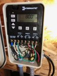
I bought a Circupool Core35 SWG. It's getting no power on circuit 3. I've attached a photo and a drawn wiring diagram. I used a multimeter on each circuit. #1 and #2 read 240V when the circuit is turned off. When circuits 1 or 2 are on, the voltage reads zero, which hopefully is an expected behavior. Circuit 3 always reads zero. The P1353ME is in Mode 2.
The first hurdle is to actually get power to the Core35.
The second hurdle--maybe not a hurdle at all--is that my Raypak heater shows a Hi Limit Fault when the pump shuts off. Is this ok? It was wired this way and seems to have been fine for almost 4 years. Perhaps there is a better way to wire the Raypak.
Thanks, all of you experts, hobbyists, and helpful contributors!
--Jason
 This assumes your diagram is correct..
")

