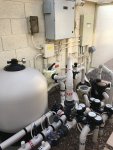
IntelliCenter OCP Load Center / Equipment Pad – Modifications and Retrofit
- Table of Contents -
- Purpose and Scope -
Note: First, it should be noted here, that nothing discussed in the initial posts of this thread are particularly necessary for the installation of basic pool automation or control. All of the methods or procedures discussed below should be considered “above and beyond”, what is necessary for most pool owners and their automation and/or equipment pad needs.
Over the last several months, I have been extremely involved in the planning and the execution of what (when fully implemented and integrated), should be quite an improvement to my current automation system.
Some may question my reasoning for pursuing such a project due to the fact that my existing automation and control system (Pentair IntelliCenter i10PS w/IntelliChlor/IntellipH) was satisfactory and sufficient. That’s true. But my motivations are not necessarily based on a “need” but rather a desire to experiment and to enjoy the “challenges” of this particular type of project.
Some may also believe that some of my methodology as will be illustrated below and my excessive "ATD", borders on insanity or in the very least, I having an over-abundance of time on my hands. No problem. It’s just a lot a whole lot of fun and keeps me "off the streets".
However, the purpose of this thread is not to discuss my new automation/sensor control system. I’m planning to share some information regarding that topic in a separate, in-depth and hopefully informative thread, just as soon as improvements and modifications have been completed regarding the software/control/reporting systems. Those improvements are certainly not my handy work by any means but are instead being developed by the super-smart guys (all members here) and that’s certainly not me. I’m only helping out with some of the initial testing.
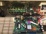
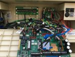
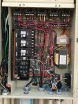
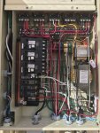
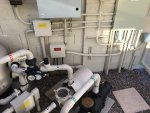
Instead, this thread concerns itself with the modifications and the retrofit of the IntelliCenter Outdoor Control Panel (OCP) Load Center, its associated junction boxes and conduits, as well as my existing automation peripherals such as the IntelliChlor, IntellipH and IntelliValves where applicable.
During the course of this discussion, I will provide photographs and/or illustrations where applicable and in some cases before/after photos where reasonable. In addition, at the end of this discussion, I will provide just a few photographs of various activities that were performed during the course of this project. Due to some size limitations and to provide for possible edits, I broke this discussion up into several posts.
And lastly, In the near future (I’m still fairly busy with the new automation/sensor project), I plan to add a follow-on post that will provide a parts list of items that were utilized during the course of this project.
UPDATE: 1/5/2021 - Since the posting of this thread, I have created and posted a follow-on companion document (see link below,) that explores the "hardware" side of this project in more detail.
 www.troublefreepool.com
- PLANNING AND OTHER CONSIDERATIONS -
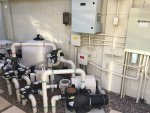
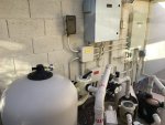
During the initial phase of planning and consultations with other members here on TFP (the darkside crew ), who had already began to explore similar and various improvements to their automation systems. It became abundantly clear to me, that if I were to incorporate the "new" with the “existing”, then a whole host of modifications and an overall retrofit to the equipment pad and the IntelliCenter OCP Load Center, really were necessary if this project were to be performed correctly and above “industry-standards”. Modularity was a key factor for me going forward and which I planned to incorporate throughout.
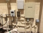
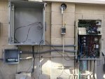
From the outset, I realized that I would need to add an additional weather proof enclosure at the equipment pad to house the new electronics that would be needed for the new automation and sensor control system. This meant a relocation of some existing items at my equipment pad such as the Equipment Pad Convenience Light and the IntellipH Controller Panel.
In addition, the elimination of the small weather proof enclosure that housed my Precision Digital pool refill flow meter/totalizer device and Lutron Caseta, WiFi Smart Switch (yes I use this instead of the IntelliCenter lighting control most times because it’s much more accurate at color selection).
And lastly, the elimination of the small enclosure that housed my LinkSys Wireless Access Point (WAP)
Note: The flow meter/totalizer, smart switch and the WAP were relocated to the new automation enclosure.
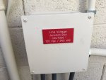
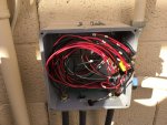 Due to the addition of the new automation enclosure and the addition of various sensors required for this project, the existing equipment pad conduits, junction boxes and power distribution and wiring (both 120vac and 240vac) would require some modifications. My existing “Line-Voltage” Junction Box required only some minor modifications however.
So, off to the “drawing board” I went. At least a month of planning and research went into this project. And I certainly thank some other TFP members here who spent some of their valuable time assisting me with the planning! I had my plans and I had my equipment shopping list and I think that I pretty much knew how I would proceed from that point (although some things were a still a bit “hazy”). And yes, there were several changes that were incorporated “mid-stream” and a good many “returns” were made to Amazon and The Home Depot, throughout the course of this project.
Since I was initially incorporating several industrial-type sensors (pH, ORP, Conductivity (EC)/H2O temp, Filter Pressure Transducer, Free Air Temp (FAT), Humidity sensor, etc. to the advanced automation system, I needed an initial connection point. Since I was adding these sensors, I figured I might as well use this connection point (junction box) for the existing automation and control peripherals as well.
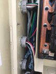
In addition, I had always been fairly dissatisfied with the way that Pentair proposes or suggests that their peripherals connect with its automation panels. A bunch of wires running up through little plastic grommets at the bottom of the low-voltage raceway of the load center? Don’t get me wrong, it’s just fine for most, but I felt that I wanted something with a “cleaner”, more professional look as well as incorporating desired modularity at the equipment pad.
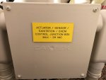
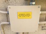
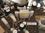
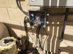
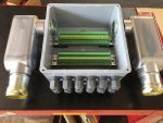
This junction box (J-box) serves as an initial connection point for the following sensors and automation peripherals: Six IntelliValve actuators (5 conductors each), IntelliChlor IC-60 (4 conductors), IntellipH power and control leads (2), Pentair H2O temp sensor (2), as well as the new pH, ORP and Conductivity (EC)/H2O Temp probes/sensors (about 10 conductors total).
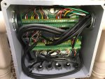
The wiring/cabling for all sensors and peripherals enter at the bottom of this J-box via the use of ½” cable glands.
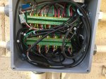
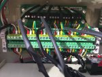
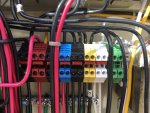
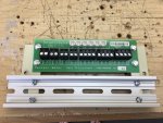
Initial connectivity is provided through the use of 30-position DIN rail mounted terminal boards as shown.
The lower terminal board within the J-box provides for the connectivity of the six IntelliValve Actuators.
The upper terminal board serves as a connection point for all other devices and sensors.
All wiring then exits this J-box via the RH 1.5” pull elbow or LB, proceeds underground and then comes up and connects with the bottom of the following J-box.
(Continued in next post)

- Table of Contents -
- Purpose and Scope
- Planning and Other Considerations
- Junction Boxes (Line, Low, Actuator/Sensor/Sanitation/Chem)
- IntelliCenter OCP Low Voltage Compartment and Raceway
- IntelliCenter High Low Voltage Compartment
- Representative Photos Page
- Purpose and Scope -
Note: First, it should be noted here, that nothing discussed in the initial posts of this thread are particularly necessary for the installation of basic pool automation or control. All of the methods or procedures discussed below should be considered “above and beyond”, what is necessary for most pool owners and their automation and/or equipment pad needs.
Over the last several months, I have been extremely involved in the planning and the execution of what (when fully implemented and integrated), should be quite an improvement to my current automation system.
Some may question my reasoning for pursuing such a project due to the fact that my existing automation and control system (Pentair IntelliCenter i10PS w/IntelliChlor/IntellipH) was satisfactory and sufficient. That’s true. But my motivations are not necessarily based on a “need” but rather a desire to experiment and to enjoy the “challenges” of this particular type of project.
Some may also believe that some of my methodology as will be illustrated below and my excessive "ATD", borders on insanity or in the very least, I having an over-abundance of time on my hands. No problem.
However, the purpose of this thread is not to discuss my new automation/sensor control system. I’m planning to share some information regarding that topic in a separate, in-depth and hopefully informative thread, just as soon as improvements and modifications have been completed regarding the software/control/reporting systems. Those improvements are certainly not my handy work by any means but are instead being developed by the super-smart guys (all members here) and that’s certainly not me. I’m only helping out with some of the initial testing.
Instead, this thread concerns itself with the modifications and the retrofit of the IntelliCenter Outdoor Control Panel (OCP) Load Center, its associated junction boxes and conduits, as well as my existing automation peripherals such as the IntelliChlor, IntellipH and IntelliValves where applicable.
During the course of this discussion, I will provide photographs and/or illustrations where applicable and in some cases before/after photos where reasonable. In addition, at the end of this discussion, I will provide just a few photographs of various activities that were performed during the course of this project. Due to some size limitations and to provide for possible edits, I broke this discussion up into several posts.
And lastly, In the near future (I’m still fairly busy with the new automation/sensor project), I plan to add a follow-on post that will provide a parts list of items that were utilized during the course of this project.
UPDATE: 1/5/2021 - Since the posting of this thread, I have created and posted a follow-on companion document (see link below,) that explores the "hardware" side of this project in more detail.
Alternative Pool Automation and Sensor/Chemical Control and Integration
Industrial Automation 8-Layer Stackable Card for Raspberry Pi Pool Automation and Sensor/Chemical Control and Integration (nodejs-poolController / nodejs-poolController-dashPanel / relayEquipmentManager) - Table of Contents - - Preface 1. Background, Purpose and Scope 2. Credits 3...
- PLANNING AND OTHER CONSIDERATIONS -
During the initial phase of planning and consultations with other members here on TFP (the darkside crew
From the outset, I realized that I would need to add an additional weather proof enclosure at the equipment pad to house the new electronics that would be needed for the new automation and sensor control system. This meant a relocation of some existing items at my equipment pad such as the Equipment Pad Convenience Light and the IntellipH Controller Panel.
In addition, the elimination of the small weather proof enclosure that housed my Precision Digital pool refill flow meter/totalizer device and Lutron Caseta, WiFi Smart Switch (yes I use this instead of the IntelliCenter lighting control most times because it’s much more accurate at color selection).
And lastly, the elimination of the small enclosure that housed my LinkSys Wireless Access Point (WAP)
Note: The flow meter/totalizer, smart switch and the WAP were relocated to the new automation enclosure.

 Due to the addition of the new automation enclosure and the addition of various sensors required for this project, the existing equipment pad conduits, junction boxes and power distribution and wiring (both 120vac and 240vac) would require some modifications. My existing “Line-Voltage” Junction Box required only some minor modifications however.
So, off to the “drawing board” I went. At least a month of planning and research went into this project. And I certainly thank some other TFP members here who spent some of their valuable time assisting me with the planning! I had my plans and I had my equipment shopping list and I think that I pretty much knew how I would proceed from that point (although some things were a still a bit “hazy”). And yes, there were several changes that were incorporated “mid-stream” and a good many “returns” were made to Amazon and The Home Depot, throughout the course of this project.
Since I was initially incorporating several industrial-type sensors (pH, ORP, Conductivity (EC)/H2O temp, Filter Pressure Transducer, Free Air Temp (FAT), Humidity sensor, etc. to the advanced automation system, I needed an initial connection point. Since I was adding these sensors, I figured I might as well use this connection point (junction box) for the existing automation and control peripherals as well.
In addition, I had always been fairly dissatisfied with the way that Pentair proposes or suggests that their peripherals connect with its automation panels. A bunch of wires running up through little plastic grommets at the bottom of the low-voltage raceway of the load center? Don’t get me wrong, it’s just fine for most, but I felt that I wanted something with a “cleaner”, more professional look as well as incorporating desired modularity at the equipment pad.

This junction box (J-box) serves as an initial connection point for the following sensors and automation peripherals: Six IntelliValve actuators (5 conductors each), IntelliChlor IC-60 (4 conductors), IntellipH power and control leads (2), Pentair H2O temp sensor (2), as well as the new pH, ORP and Conductivity (EC)/H2O Temp probes/sensors (about 10 conductors total).

The wiring/cabling for all sensors and peripherals enter at the bottom of this J-box via the use of ½” cable glands.
Initial connectivity is provided through the use of 30-position DIN rail mounted terminal boards as shown.
The lower terminal board within the J-box provides for the connectivity of the six IntelliValve Actuators.
The upper terminal board serves as a connection point for all other devices and sensors.
All wiring then exits this J-box via the RH 1.5” pull elbow or LB, proceeds underground and then comes up and connects with the bottom of the following J-box.
(Continued in next post)
Last edited:


