- Jun 30, 2020
- 55
- Pool Size
- 11000
- Surface
- Plaster
- Chlorine
- Salt Water Generator
- SWG Type
- Pentair Intellichlor IC-40
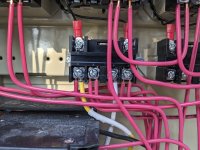
Correct. Only that relay is reversed.Scary thing is, looking at the relays, the only thing consistent is the inconsistencies
Edit - looking closer, it appears only the relay with the swg transformer has line and load reversed from conventions.