In Floor Cleaning System - How Should it Work?

Pump speeds might be deceiving. I've changed them to try to get the IFCS to stop getting water all over the coping. I'm pretty good about taking photos before I mess with things too much and found the attached speeds from March. Maybe they make more sense?
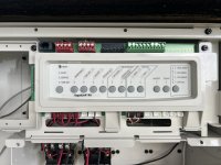
I think you missed my point. On your screen shot - in the upper right it states Pump 1. But pump 1 is the filtration pump and Pump 2 is the Cleaner pump. So what is scheduled for Pump 1 should not affect IFCS - based on what I see.

What we do not know is what all those return pipes lead to against that back wall. Is it feasible to track where the output of pump 2 (the one on the right side) leads to? My thinking is that there are 2 suction lines to that pump then there must me 2 return pipes going to the pool that has a valve that allows you to switch between one or the other. I suspect one leads to your octopus device which is your IFCS hub.

The main pool has one large circle drain looking thing at the deep end. I'm pretty sure this is the IFCS drain. The basin has 3 things: a drain that is in the center of the basin on the wall, and 2 circle drain looking things at the bottom (so likely connected and considered a set?) on the side closest to the overflow and auto-filler. The spa has 1 drain on the wall, one on the floor.
Usually a wall drain is used when the suction through it does not need to go through the filter. It is off the floor so no debris enters it - just water. They are used for a waterfall or maybe even the vanishing edge. What you describe makes me think as follows

The large main drain on pool bottom is for main filtration pump - as the IFCS pushes debris to it, you want the filter to capture the debris.
In the basin - the bottom drain must be for the filtration pump as well and the wall drain - not sure.
Since the spa has 2 differeent types of return jets - I am assuming one is high rate and linked to one of the suction drains.

The pump 2 only has Vanishing edge scheduled on it so that should run regardless if filter pump is on or not. I wanted to give you some initial feedback and I am still thinking through your setup design.
 
@HermanTX

Why does the the IFCS pump #2 shut off when she only shuts off the Main filter pump #1???

Does the automation have some kind of group control???

Thanks,

Jim R.
I am researching that now. I think IFCS acts like a SWCG on internal programming. If the main pump is off then the IFCS is off and visa versa. The 2 pumps have me confused unless there is wiring from one relay to the other.
 
@LynnOnTheWeb
If you are comfortable with removing the panel in front of the AquaLink panel, it is needed to understand how your pumps are wired to a relay or maybe not to any relay. Below is a photo of how the panel looks. It does not show the circuit breakers which would be below those relays.
There are 2 pumps. Each pump should have its own circuit breaker and each CB should be a 240V (double handles). The pump wires should connect into the CB or they may connect to one of the relays. This would be the large conduit leading from the back of the pump into the AquaLink Cabinet. Take a picture of each pump wiring.

Also, there should be a small diameter wire - we call it a RS485 that leads from the pump to a RED connector on the computer board. Can you snap picture of that as well.
Understanding where your pumps are powered from and how they are controlled will help troubleshoot what happens when 1 pump is turned off.
Sorry for crude hand sketch
IMG_0410.pngIMG_0412.png
 
I took these the other day. I’m not at the house right now but I’ll open it up again late tomorrow and get better photos that include the breakers. I think one of them goes through a relay and the other is only wired to the breaker.
 

Attachments

  • IMG_6341.jpeg
    IMG_6341.jpeg
    343.4 KB · Views: 12
  • IMG_6342.jpeg
    IMG_6342.jpeg
    363.1 KB · Views: 10
  • IMG_6343.jpeg
    IMG_6343.jpeg
    331.6 KB · Views: 12
  • IMG_6344.jpeg
    IMG_6344.jpeg
    384.8 KB · Views: 12
Lynn,

Based on your pics, you only have 4 relays that are connected... Aux 1, 2, 3, and 4. This would be for your Pool light, Spa light, Water feature light, and Spa blower..

This means that the two pumps cannot be connected to any of the relays and are being controlled by your RS-485 com port..

This means the operation of the two pumps are linked via some kind of programming..

Thanks,

Jim R.
 
  • Like
Reactions: HermanTX
I am in agreement with @Jimrahbe that both pumps are being controlled by the RS485 cables. I see there is a wire connected to both RED connectors on the PCB.
Your schedule shows that the filter pump (noted as Pump 1 on your setup screens) runs for 9 hrs and 1 min and the Vanishing edge/Cleaner Pump (pump 2 - the one on the right side) runs for 23 hrs and 59 mins. Those are the only 2 items that are scheduled. Does the filter pump run its 9 hr schedule OK?

The 3 way suction valve on the pump 2 is open to both pipes marked as Cleaner and Main Drain. Therefore when this pump is on (for 24 hr operation) it is activating both the cleaner and pushing water over the vanishing edge.
Have you tried to rotate the valve handle such that the word CLOSED on the handle is facing the pipe marked CLEANER?

It is very hard to make out the return side, I watched your video several times but unable to follow the piping from the Pump #2 to the return. Can you follow the pipes leading from the Pump #2?

Also, could you take a picture of your basin showing the drains on bottom and also the wall flowing over from the pool into the basin?
 
I remembered that Jandy ePumps need to change the dipswitch on the pump so the automation system knows which pump is which. This requires to open the cover on the pump electrical connection.

Each pump is assigned an address of 1 through 4 using Dip Switches 3-4 on the pump. Use the table below for pump address assignment settings. These settings are used when connected to the RS485 connection on the pump or when connected to the pump using a SpeedSet controller’s automation pass-through wiring connection on the bottom of the controller.
Address Switch 3 Switch 4
Pump 1 OFF OFF
Pump 2 ON OFF
Pump 3 OFF ON
Pump 4 ON ON

It would be good to verify that each pump has its only address.
Jandy Pump Junction Box Dip Switch Highlighted.JPG
 
Yes, pump 1 runs its schedule as it is in the programming. Pump 2 seems to run the same schedule though.

I have tried to rotate the valve on the cleaner, the cleaner doesn’t turn off when when I turn it to “Off.” These are my observations. Turning off cleaner there is no perceptible difference in the IFCS or the overflow. If I switch off drain, the water levels in the filter basket attached to the pump seems to drop a little, but it also raises and lowers some. It never emptys, just drops a couple of inches and never fully fills. Turning the inlet off empties the basket completely. I don't know if it turns off the IFCS or vanishing edge because I didn't want to risk running the pump dry.

2 videos are attached. One chasing the pipes from the pumps, the other showing the drains in the basin and the jets in the wall. Let me know if you prefer stills.

In addition to the videos, I’ve attached the breakers labeled as they are on the panel and a photo of the dip switches. They all look off to me. Yes the PB didn’t install GFCI breakers. Again, don’t get me started on him. We’ve ordered and are installing a GFCI breaker at the panel.


IMG_6395.jpegIMG_6394.jpeg
 

Enjoying this content?

Support TFP with a donation.

Give Support
Turning off cleaner there is no perceptible difference in the IFCS or the overflow. If I switch off drain, the water levels in the filter basket attached to the pump seems to drop a little, but it also raises and lowers some. It never emptys, just drops a couple of inches and never fully fills. Turning the inlet off empties the basket completely. I don't know if it turns off the IFCS or vanishing edge because I didn't want to risk running the pump dry.
Lynn,

You should be able to turn off the "Cleaner" pipe or the "Main Drain" pipe without any problems at all.. But... You never, ever what to rotate that valve so the it shuts off all the water going to the pump.

You should be able to shut off the "Main Drain" pipe and the pump should not run out of water. I suspect the water in the pump is moving up and down as the water level in the pool changes from spillover to no spillover.

I recommend you shut off the "Main Drain on the #2 pump, what a minute and then go see of the spillover has quit. Then turn the spillover back on.

I do not see a breaker that is just for pump #2.. I assume the double pole breaker on right that feeds the UV, heater also feeds Pump #2..

As a quick test, shut off the double pole breaker on the right and see if pump #2 shuts off.. It will not hurt anything.. While Pump #2 is off confirm that your spillover stops.. Then turn it back on.

Are you saying that both pumps only run from8Am until 5 pm????

Thanks,

Jim R.
 
Yes, pump 1 runs its schedule as it is in the programming. Pump 2 seems to run the same schedule though.
This has me thinking that Pump #2 is not Addressed as Pump #2 - see my post in #29.
It would be good to confirm that the pumps are addressed - if not then they could run the same schedule.

Alternatively, I would delete the schedule for Vanishing Edge and see if Pump #2 turns on. It should not as that is the only schedule for it on your screen shot.
 
Gentlemen, we have progress!!

This has me thinking that Pump #2 is not Addressed as Pump #2 - see my post in #29.
It would be good to confirm that the pumps are addressed - if not then they could run the same schedule.
I misunderstood this. These are dipswitches INSIDE the pump not on the panel. I opened up pump 2. Dipswitches were wrong. I changed them and now pump 2 behaves as pump 2. Vanishing Edge option in my iAqualink controls it now.

I changed the videos to public, the videos should be good to go and I relinked them here for you.


I recommend you shut off the "Main Drain on the #2 pump, what a minute and then go see of the spillover has quit. Then turn the spillover back on.
I've done this and don't see an obvious change. This valve only seems to shut off the inlet if it's in that position (I know, that will burn a pump up. Don't worry I'm not putting it in that position but I did check it). No other setting seems to do anything.

=====================================
From here below might be mostly irrelevant now since the dipswitches got changed but I answered these before the change so I'll leave them just in case.

Are you saying that both pumps only run from8Am until 5 pm????
They were. Now that the dipswitches are changed I'm guessing it will run on the schedule.

As a quick test, shut off the double pole breaker on the right and see if pump #2 shuts off.. It will not hurt anything.. While Pump #2 is off confirm that your spillover stops.. Then turn it back on.

Spillover and cleaners stop when pump 2 is turned off at the breaker. Even with valve to "off" at "cleaner" IFCS comes back on when pump 2 is turned back on at the breaker. Turning the valve to "off" on "main drain" doesn't stop the spillover but it gurgles a lot.

Alternatively, I would delete the schedule for Vanishing Edge and see if Pump #2 turns on. It should not as that is the only schedule for it on your screen shot.

I never did this because I wasn't sure how to delete it. I see the screen option for vanishing edge but not how it's programmed in iAqualink. Or more accurately, I see the pump 2 programming but not how it's connected to the switch on my screen in iAqualink.

My advice after looking at this is to rewire everything. Was this done professionally?

Presumably. But it wasn't done with GFCI breakers so there's that.
 
hese are dipswitches INSIDE the pump not on the panel. I opened up pump 2. Dipswitches were wrong. I changed them and now pump 2 behaves as pump 2. Vanishing Edge option in my iAqualink controls it now.


Excellent!!! :goodjob: I'm glad Herman got you pointed in the right direction...

So, where are we now? We have all been running around in circles so I'm a little lost.. :mrgreen:

What is it you want the pool to do, that it is not doing now that you have the pumps working like they should..??

Thanks,

Jim R.
 
  • Like
Reactions: HermanTX
I misunderstood this. These are dipswitches INSIDE the pump not on the panel. I opened up pump 2. Dipswitches were wrong. I changed them and now pump 2 behaves as pump 2. Vanishing Edge option in my iAqualink controls it now.
This is great news and now the schedule that is set should work independently. Run it for a day and be sure.
If there are additional questions on programing let me know.

The Pump on the right controls the IFCS. The pump on the left is the primary filter pump. Which of those pumps turns off at 5pm (based on your earlier screenshot - 1 pump ran for 9 hrs and the other ran 24 hrs. )

Thanks for the videos - they were helpful.
 
As setup, the pump that turns off at 5 is the main filter pump (pump 1). The cleaner and vanishing edge are set to run all day/night (pump 2).

The only thing in the IFCS is still like to be able to do is turn off that and have the vanishing edge still run. I don’t understand what that 3-way valve is doing, it doesn’t seem to turn off the IFCS water flow. Should it do that or am I misunderstanding it’s purpose?

At then end of the day, if that’s not possible, I’m still thrilled. Not being able to shut that pump off (which turned off the IFCS) and still have the other pump running (which also heats the hot tub) was super irritating.

I’m forever indebted.
 
  • Like
Reactions: Jimrahbe
The only thing in the IFCS is still like to be able to do is turn off that and have the vanishing edge still run. I don’t understand what that 3-way valve is doing, it doesn’t seem to turn off the IFCS water flow. Should it do that or am I misunderstanding it’s purpose?
That 3way valve is on the suction side - so that does not dictate where flow goes - only where it comes from. That far right pump only leads to the IFCS so that it its main function. I do not see a Tee off of it to another return that may go to the vanishing edge only. To affect the return, there needs to be some valving on that side. Looking at your original picture - the far right side has 6 pipes numbered 1-6. my guess is that leads to the various zones for your pool. Trial and error you can turn that blue handle off on one line and see which zone does not operate. Also remember that the octopus device controls which zone of the IFCS operates as there is a sequence. So it may not be immediate as to which zone did not work - as you have to let it go through a sequence. Do not turn them all off at the same time. Alternately, did the PB leave any diagram of how the zones were set up for the pool? That would be very helpful.

Pipework.jpg

I am also confused by the 3-way valve on the suction side of the #2 pump. It is split suction between the cleaner and the pool. The issue is, there is nothing telling us where those suction drains are located. My guess is that one of them is in the basin, but you have one set of drains on the floor and some other type of drain on the wall (that was hard to see in the video). On the pipe marked pool - again no idea where that is sucking water from.
Need to ask as not sure this was given - did you have the pool put in or was it existing when you purchased the home? I think you said you were frustrated with the PB so maybe he has some drawings of the plumbing that you can request.
 
Thanks for the additional info on the IFCS. I was thinking that the valve controlled the water to the system, not that it was suction but now that you've pointed it out, it makes sense. I'll check the pipes i the back.

Interestingly though, now that everything is working property with the pumps, it's not as big of a deal that the cleaners are running all the time with the vanishing edge for a couple of reasons:
  • We can turn them off when using the spa.
  • We've noticed that they aren't pushing out a crazy volume of water now. I assume it's because they don't have as much pressure. We can tell they are running because they pop up and the water moves a little in the area, but before they were making the water jump onto the coping on the more shallow heads and that's not happening anymore.
I'm still going to see if I can figure out how to shut it off completely, but if I can't figure it out I'm letting this one go. It's no longer the source of frustration that it was since we can at least control it now.

There is a pipe labeled vacuum with the returns so that part seems clear. The only return label that puzzles me is one labeled BB.

I am also confused by the 3-way valve on the suction side of the #2 pump. It is split suction between the cleaner and the pool. The issue is, there is nothing telling us where those suction drains are located. My guess is that one of them is in the basin, but you have one set of drains on the floor and some other type of drain on the wall (that was hard to see in the video). On the pipe marked pool - again no idea where that is sucking water from.
Need to ask as not sure this was given - did you have the pool put in or was it existing when you purchased the home? I think you said you were frustrated with the PB so maybe he has some drawings of the plumbing that you can request.

I'm pretty sure the main drain is the one on the wall of the basin. When I shut it off, there is a lot of gurgling from it. Cleaner is likely the one in the bottom of the deep end of the pool That's a different type of drain and all the debris is pushed to it.

Yes, I know who the PB is. I'm a home builder and he's built 10+ pools for me but things went way south on this one (it's my personal pool) when he built it 18" too short and I had to get my lawyer involved to get him to fix it. I'd need to go through lawyers to get drawings, which I'm not sure he has anyway.
 

Enjoying this content?

Support TFP with a donation.

Give Support
Thread Status
Hello , This thread has been inactive for over 60 days. New postings here are unlikely to be seen or responded to by other members. For better visibility, consider Starting A New Thread.