Bermuda Skimmers - Gunite
Our bermuda gunite skimmers are engineered and manufactured to the highest standards of precision and quality to minimize installation time and maximize satisfaction.
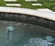
Bermuda Skimmer and White Goods Kits
Our bermuda skimmers and white goods kits are engineered and manufactured to the highest standards of precision and quality to minimize installation time and maximize satisfaction.