IC60 & IntelliPH no longer working (5 months old) - Input?

hey @Zaffor, refer to the photo below...

with the iph disconnected, I want to know if either of the 2 pins that connect to the pc board trace with the red marking (this is Vdc, the supply voltage) have continuity to any of the 4 pins surrounded by the yellow box (these are the data lines, 2 white, 2 green).

View attachment 421915

Set your meter to continuity... then put one meter probe on one of the red pins (they're both the same), and touch the other probe to each of the pins in the yellow box... see if you get a beep. then do the same with the 2 pins that connect to the trace with the black marking.
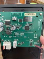
4C570D28-F5BF-42F4-BB21-C5DF67EF071E.jpeg
No continuity between either dc pins with data pins. At least not on this iph board.
 
@Zaffor, perhaps the results will be the same, but those aren't the red and black pins (at least not on my board), it goes, from left to right in your pic:

white - green - black - red

Tom had mentioned that when you flip the board, the pin arrangement will be mirrored to his pic, which was taken of the underside of the board.

They labeled nearly everything else on that circuit board, but left those pins unlabeled!!

Also, there are four data pins, two of which might be tough to get to from above. I suppose you could measure the data pins via the conductors inside the connector, but if the board stopped working you should use the external pins for the red and black.
 
Last edited:
@Zaffor, perhaps the results will be the same, but those aren't the red and black pins (at least not on my board), it goes, from left to right in your pic:

white - green - black - red

Tom had mentioned that when you flip the board, the pin arrangement will be mirrored to his pic, which was taken of the underside of the board.

They labeled nearly everything else on that circuit board, but left those pins unlabeled!!

Also, there are four data pins, two of which might be tough to get to from above. I suppose you could measure the data pins via the conductors inside the connector, but if the board stopped working you should use the external pins for the red and black.
Your right I painted it backwards. There is still no continuity from vdc to communication. Actually I tested between all four points to each other and there was no continuity on any.
 
  • Like
Reactions: Dirk
@ogdento is there a way I can test the surge board to find out whats going on with it? My cell acts like it’s working fine yet it is not creating (or not creating the correct amount of) chlorine. It was easy to isolate it as a problem when it had shorted or overheated components but as of now it “looks” fine.
 
You could check the voltage across the red and black, and watch to see if it varies over time. I expect it will drop when the SWG is producing vs when it is idle, but you want the voltage to be consistent during each part of the cycle (I think).

We've done a pretty good job of hijacking @tomas21's thread, unfortunately. I had to go back and see who's problem was who's. I'm not sure what to do about that. I could have your posts moved to a new thread, where we could deal with your IC60 output problem as a separate issue. But they're tangled up pretty good at this point. Or as you asked previously, you could start your own.

Your IC60 problem could be a chemical one. How are you determining that the IC's output is varying? Just by measuring FC in the pool? That could actually be some sort of intermittent algae issue. I'm not sure how best to isolate the IC60, in terms of testing only its output without any interference from the pool. Others who might know probably won't be looking to help here, because they've already written off Tomas' thread as "handled" by us IntellipH fixers.

@Jimrahbe, how best to take care of @Zaffor?
 
Last edited:
@Zaffor i don't have a surge board on my system and i'm not entirely sure how it's connected, but as far as i know, it performs 2 functions - maybe somebody can tell me if i'm correct...
1. the large on-board bridge rectifier converts the SWG transformer's AC output to DC - so you can check to see if you get ~30vdc out of it
2. adds 3 extra comm port connectors (comm port Vdc/red is not connected to the surge board Vdc, but the comm port Ground/black IS connected to the surge board ground - and the TVS diodes on the data lines DO connect to the surge board ground)
 
Hey @Dirk i was chatting with @rstrouse... it might be useful to have a (separate?) thread that captures/compiles some data from all these failures...
- who's board is it
- date of failure
- any known storm/surge events
- SWG cell type and operation duration
- which wire(s) are scorched on the connector
- were the comms fried (any of the comm parts... rs485 chip, tvs diodes, relay)
- if any traces burned up
- if the surge board's tvs diodes burned
 
  • Like
Reactions: bertschb
Absolutely. I lost track of all that many cases ago. I've been amazed you've been keeping track as well as you have been! Not sure how best to proceed with that, though. Are you volunteering? ;)

It should all be in one post, the first one. As new cases arise, and the thread grows, the OP could edit the details into that original post. Because surely there will be many commenters in the thread, and so subsequent cases would just get lost in the shuffle. The thread could house example pics, perhaps our "fix" illustrations, etc. Felipe and I were discussing something similar, back around post #50.

Or maybe a wiki article. Not sure which is best.
 
actually yeah maybe a single post with the start of it being the main table of data, and we can go back and update it as needed. kindof like what jerry did for the pentair easytouch/intellitouch firmware update thread. let me compile what i've got and i'll get something posted.
 
  • Love
  • Like
Reactions: Dirk and bertschb

Enjoying this content?

Support TFP with a donation.

Give Support
You could check the voltage across the red and black, and watch to see if it varies over time. I expect it will drop when the SWG is producing vs when it is idle, but you want the voltage to be consistent during each part of the cycle (I think).

We've done a pretty good job of hijacking @tomas21's thread, unfortunately. I had to go back and see who's problem was who's. I'm not sure what to do about that. I could have your posts moved to a new thread, where we could deal with your IC60 output problem as a separate issue. But they're tangled up pretty good at this point. Or as you asked previously, you could start your own.

Your IC60 problem could be a chemical one. How are you determining that the IC's output is varying? Just by measuring FC in the pool? That could actually be some sort of intermittent algae issue. I'm not sure how best to isolate the IC60, in terms of testing only its output without any interference from the pool. Others who might know probably won't be looking to help here, because they've already written off Tomas' thread as "handled" by us IntellipH fixers.

@Jimrahbe, how best to take care of @Zaffor?
I can create a new post if you think thats best. I figure its related to this issue though. Perhaps the iph trouble causes some damage to the surge card? Or could it be the opposite and the surge card causes the damage to the iph? Maybe its totally unrelated and it was just coincidence? I do know i was having the no/low chlorine output for a while before the iph/surge card failure. As soon as they swapped out the surge card my chlorine output resolved. Now its acting up again. The third issue was the iph locking up on me periodically. Related? Maybe, maybe not! I wish I knew what was going on in there. I will check the voltage on the surge card output. Cant be chemical balance as the liquid chlorine I add works fine. Pool is crystal clear.
 
I should add, my pool is only 15,000g. At 100% running 24hrs/day that IC60 should be making large amounts of excess chlorine
 
I can create a new post if you think thats best. I figure its related to this issue though. Perhaps the iph trouble causes some damage to the surge card? Or could it be the opposite and the surge card causes the damage to the iph? Maybe its totally unrelated and it was just coincidence? I do know i was having the no/low chlorine output for a while before the iph/surge card failure. As soon as they swapped out the surge card my chlorine output resolved. Now its acting up again. The third issue was the iph locking up on me periodically. Related? Maybe, maybe not! I wish I knew what was going on in there. I will check the voltage on the surge card output. Cant be chemical balance as the liquid chlorine I add works fine. Pool is crystal clear.
No, you didn't quite get what I was saying. There's not much more I can do for you regarding the IC60 intermittent output issue. I've never heard of that, and don't know what to suggest. Notice, no one else has offered anything either, other than Tom suggesting you check the voltage. Others, that might be able to help, are not likely going to even find your posts about it, because this thread was (1) started by someone else, and (2) his problem has pretty much been resolved by Tom and me. Notice, he's not even been around. Plus, it's four pages long now, and it's quite an ask to bring in others to wade through all that to catch up. If you start your own thread, and put your problem into post #1, you stand a better chance of getting noticed by someone that might have some ideas. That's all.

And for the record, a "crystal clear" pool does not mean it's algae free. Or that there might not be some other issue that is consuming FC.

So yes, I believe it's in your best interest to start a new thread. You're welcome to continue here, if you like, but technically hijacking is discouraged, because it distracts from the OP's issues and isn't the best way to solve your own. Come back to this one if you do start one, and post a link to it, so any following along here will know where you went...
I will start over and try to explain it in first post
 
  • Like
Reactions: Dirk
Created a new post explaining as best I could. Thanks again!
 
@Lake Placid reports today that he tried "the fix" and, well, it fixed! He used variation #3, where the original wires and connector were left in place, and he ran two jumpers to splice the red and black wires before they get to the connector, and two more to bypass the red and black conductors of the faulty connector.

He also reported that he observed corrosion on the connector pins, before he noticed any burn marks, which was causing intermittent IntelliChlor behavior. Then later his IC stopped working altogether, at which point he did observe a slight burn on the connector.

Edit: Later the intermittent behavior got worse and then he observed the a slight burn mark.

He also used a product called deoxit after cleaning the connector pins (this was after first noticing corrosion), but ultimately the connector burned and failed anyway.

Thanks for giving the fix a go, Lake Placid, and for the report.

 
Last edited:
  • Like
Reactions: bertschb
@Lake Placid reports today that he tried "the fix" and, well, it fixed! He used variation #3, where the original wires and connector were left in place, and he ran two jumpers to splice the red and black wires before they get to the connector, and two more to bypass the red and black conductors of the faulty connector.

He also reported that he observed corrosion on the connector pins, before he noticed any burn marks, which was causing intermittent IntelliChlor behavior. Then later his IC stopped working altogether, at which point he did observe a slight burn on the connector.

He also used a product called deoxit after cleaning the connector pins (this was after first noticing corrosion), but ultimately the connector burned and failed anyway.

Thanks for giving the fix a go, Lake Placid, and for the report.

Just to clarify my IC never fully stopped working, it just went into an infinite loop of restarting when I noted the corrosion and slight pin burn.
 
  • Like
Reactions: Dirk

Enjoying this content?

Support TFP with a donation.

Give Support
Thread Status
Hello , This thread has been inactive for over 60 days. New postings here are unlikely to be seen or responded to by other members. For better visibility, consider Starting A New Thread.