I want to control multiple Hayward VSP with Arduino Board

zafarpatel7

Active member
Sep 1, 2019
31
india
Hello All
Good Morning

I prepare some automation controllers on Arduino Board. so with the help of RS485 port, I am able to controller single Hayward VSP below is the packet to control Hayward VSP @ 100% speed and it working perfectly
ex. [ 0x10, 0x02, 0x0C, 0x01, 0x00, 0x64, 0x00, 0x83, 0x10, 0x03]

[START OF PACKET BYTES]: 2-bytes fix bytes which indicates Start of Packet [0x10 0x02]
[DESTINATION ADD] : 1- Byte Destination Address [0x0C]
[SOURCE ADD] : 1- Byte Source Address [0x01]
[FIX BYTE] : 1- Byte fix byte [0x00]
[DATA] : 1- byte Data - RPM Data in Parentage 0% - 100% [0x64]
[CHECKSUM] : 2 Byte Checksum [0x00 0x83]
[END OF PACKET BYTES]: 2-bytes fix bytes which indicates END of Packet [0x10 0x03]

---------------------------
Now Problem is I want to control 3 Hayward Pump with the same Arduino Board, but as per RS485 protocol, all Hayward VSL should have different Slave addresses.

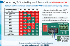
and I seen in Hayward VSP terminal side, it has the same DIP switch - and as per my study this DIP switch is used for setting the different Slave addresses (please check doc in the attachment )

so when I keep all DIP switch ALL OFF or only 2nd DIP switch ON -- so I am able to control VSP with 0x0C (12) slave address

But I was not able to find other slave addresses with respect to the DIP switch, anyone could we help me on this how-to identify Hayward VSP address and my understanding is correct or NOT ?
1626621297968.png

Thanks in advance
 

Attachments

  • tristar-vs-QRG3201VSP-RevA.pdf
    816.5 KB · Views: 34
From your diagram it looks like the logic to control multiple pumps is contained within the controller and not on the pump itself. The controller looks like it is deciding which AUX port to send the (same) signal to the pump on. Perhaps you can get an Arduino board that has addressable outputs for RS485 which you would use to control which pump gets the output.
 
Thanks for your response

Main Controller is Master -- and all VSP is slave as per RS485 -- And As per RS485 protocol --- Master only Send queries to slave with the of slave address -- So as per my study I agree on your point - hope you understand my point
 
I recognize that packet structure. This looks a lot like the packets that are used to control various brands of chlorinators.

The packet always starts with [16,2] or [0x10, 0x02]. It is then followed by a destination address. For instance, to refer to consumer grade chlorinators you use 80 or 0x50 for the command request. If this is a chlorinator array then the addresses increment based upon the set address in the controller. Responses will come back using the equipment identifier set on the receiver. So 80 returns 0 and 81 (if you have a commercial unit) returns 1. After the destination address comes the action byte (register). This identifies what response you want from the equipment.

I am going to describe the message bytes in decimal because it is easier to see the values.

For chlorinators the request actions are as follows:
0 = Disable external control
17 = Set level
20 = Get model

The responses from said actions are:
0 => 1 = The returned payload contains 0,0 if there are no faults on the unit and it was successful.
17 => 18 = The returned payload contains the current salt level (byte(0) x 50) and an encode status byte for alarms on the controller.
20 => 3 = The returned payload is a 16 byte ascii string with the model.

After the action byte comes the payload. The payload contains as many bytes as necessary to cover the requested information.

The next byte is a checksum. However, this is typically only one byte long and includes the 16,2 preamble. In your example above, given my experience with this you have 2 bytes of data and 1 checksum byte.

The final sequence is the terminator for the message and is always [16,3] or [0x10, 0x03].

So a packet for a request to get the model in decimal is:
[16, 2, 80, 20][0][118, 16, 3]
and the response is:
[16, 2, 0, 3][0, 73, 110, 116, 101, 108, 108, 105, 99, 104, 108, 111, 114, 45, 45, 52, 48][188, 16, 3]
1626633067091.png

I think you will find that your pump probably follows this protocol pretty closely.

The key is to decode the action bytes and the responses. For most other pumps there is a completely different protocol that uses a [255, 0, 255] preamble.
1626633313264.png
 
  • Like
Reactions: cmc0619

Thanks @rstrouse

very good details you shared

and after the Destination address, I saw the source address, So the source is the controller and the destination is VSP and based on this understanding I prepared one script which sends data to one by one with a different address from 1 to 247(as per RS485 protocol address)

so what I did exactly I keep DIP switch AUX3 position ( #1-OFF, #2-ON, #3-ON, #4-OFF, #5-OFF) - please refer above DIP switch table

and after that, I send VSP Run Command one by one, I change only the destination address and Source address fix - 0x01

from -
[ 0x10, 0x02, 0x01, 0x01, 0x00, 0x64, 0x00, 0x83, 0x10, 0x03]
.
.
.
.
[ 0x10, 0x02, 0xF7, 0x01, 0x00, 0x64, 0x00, 0x83, 0x10, 0x03]

so can I change the source address as well?
 
You also need to look on the bus because there will be returns from the pump for all messages you send it. I realize this is Hayward but much of the 16,2 --> 16,3 protocol is shared between manufacturers. There is no source address from the master to the slave in this protocol. You will only see this on the return/response from the slave at byte index 2. That 0x1 is not a source address it is the action/register byte.

To talk to a pump on a different address. The most logical thing is the change the dip switches to another value then the pump should respond on a different value for byte index 2. So it sounds like you need to change the dip switches then see what address you can communicate on. Interestingly your 0x0C address is 0000 1100 in binary. 0000 0100 = 0x08 | 0000 1000 = 0x04 are good potential candidates for the Aux 2 address.

Byte index 3 is the command or register byte. This identifies what is in the payload. So the packet/message you are sending on the bus it action 1. The pump is likely responding with another action using this same 16,2 --> 16,3 protocol. You should not place another command on the bus until you read the bus for the response. The response will likely be the command acknowledgement (ACK) as well as a payload containing any information reported by the pump (drive state, wattage, rpm... etc). Bear in mind I don't have this pump I am simply reflecting what I have experienced from other pumps and this protocol.

Bear in mind there will be more than one protocol on the bus if there is a master controller in the mix. These typically use a preamble of [255, 0, 255] followed by a header [<proto id (165 in Pentair)><channel><dest><source><action><payload length>][<payload>][<checksum hi><checksum lo>]. So if you see a byte preamble like this (255,0,255) the pump also reports status to a standard controller.
 
I configured DIP swicth as a AUX2 - #2- ON others are OFF, and send all the belwo command from PC, i have not got any reponse from

1626805290133.png

1626803985511.png

But when I am keeping all DIP switch OFF (or Only #1-ON others are OFF) so able to control and getting the response

1626805230458.png


1626805170028.png


for Hayrad VSP protocal implemetaion I got help from below form link, please take a look on it --

and for Pentair

Please check ablove link if you get some extra information
 
I can tell you that the two Pentair articles are only partially correct. I haven't examined the output for this pump though.

Interestingly, in the Pentair world 0x0C is the address that is used for devices that have not been addressed. Most notably iChlor, UltraTemp, and IntelliValve broadcast periodically on this address when they do not have an address assigned to them.

That being said there is definitely a 2 byte checksum in your returns which completely changes the protocol around. Interestingly, the Hayward AquaRite chlorinators have only a one byte checksum and do communicate on address 80 [0x50] just like the Pentair ones do. That would mean the controller is dealing with 2 distinct protocol layouts if both pieces of this equipment are on the bus which I assume would be the case if you had Hayward gear. One that has a 2 byte checksum and one that has a 1 byte checksum.

Further, there does appear to be a source and destination address. I wonder what response you would get if you set the dip switches to Aux 1 and sent 10 02 0D 01 00 64 00 84 10 03.
 
with Pentair I am good, I don't have any issues on it -- able to control multiple VSP in the same RS485 bus,
and regarding Hayward only controlling the Multiple VSP is the issues

dip switches to Aux 1 and sent 10 02 0D 01 00 64 00 84 10 03. - I already tried but not got success
 

Enjoying this content?

Support TFP with a donation.

Give Support
@ccbill,

Interesting timing! I just spent yesterday morning using that API document to communicate with my Vgreen165 and that document and commands do seem to be correct for Modbus protocol that the motor uses.

I was able to read the status register and read and write the configuration registers. I didn’t actually control the motor but there’s no doubt in my mind those commands work.

A little background, I installed a Jandy Aqualink RS system in December and had to work out how to control my Vgreen motor. I ended up using extra relays and the four digital inputs to select four motor speeds. That worked great and I’m still using it that way.

In that API document one of the configuration variables (page 10, address 05) says it selects the user protocol and the choices include the big three pool vendors and an “all in one” choice.

This intrigued me as I though it might be possible to change that configuration variable and have the motor then talk the Jandy protocol of my automation system

I was able to read that configuration address and other addresses on page 10 (0x0A). I checked the register values to see if they made sense relative to what was in that API document. The values in the priming speed registers were the hex value equivalent to 2600 rpm and the other register values made sense also.

The value of page 10, address 0x05 was 0, which is the default protocol. I tried writing this register with 4 to set the motor to all protocols, but that write failed indicating that 4 was not a valid argument. I then tried the value 1 to set it for the Jandy protocol and that took and I was able to also write it to flash and have it persist across a power cycle.

But the motor didn’t recognize the Jandy motor commands as I had previously captured the commands from my Aqualink RS system. I tried all the four standard Jandy addresses and also the Modbus address of 0x15. No joy on the motor understanding the Jandy protocol but it just continued to respond to the modbus commands as detailed in that document.

To talk to the motor I was using a serial terminal program that had the ability to send hex values and a $14 dollar USB to RS485 converter that I found on Amazon.

Figuring out the checksum for the commands had me stumped until I asked a programmer friend about it. He pointed out that it is a standard CRC16 modbus checksum and he pointed me to an online checksum calculator at www.crccalc.com

To use that calculator chose hex for both the input and output types and then enter the command string you want to send with no spaces. For the status command its 154320 and then press Calc CRC16. then scroll down the list of results until you see CRC-16 / MODBUS and you will see the result is 0xEC50.

So the full command plus checksum is 0x15 0x43 0x20 0x50 0xEC. When this is sent to the motor it responses back as it should.

I can see in the Jandy protocol that it is trying to execute commands 0x44 (set Demand) and then 0x41 (go) in its protocol and these commands make sense based on the API document.

I imagine that my attempt to set the motor to the Jandy protocol failed because the generic RBC code on that motor doesn’t support anything but the modbus protocol.

While I wasn’t successful in that endeavor I did verify that that API is correct, and the motor can be successfully read and written using those commands.

It was a fun exercise to figure out, maybe this info will help someone else. If anyone needs some examples of command strings with their checksums I will be happy to share what worked for me.

Mark
 

Attachments

  • Gen3 EPC Modbus Communication Protocol _Rev4.17.pdf
    379.2 KB · Views: 437
Last edited:
  • Like
Reactions: brentk
@MSchutzer , thnx for the response that is good to hear. I'm new here and read the forum rules after I posted - I may have inadvertently hijacked this thread which is about Hayward VSP specific rather than hacking automation in general. I'll create another topic ...
 
@rstrouse suggested you explore byte index 4 to see if it matched any of the aux dip switch settings. Did you try that?

I see Hayward Unique Address (HUA) mentioned regarding controlling multiple pumps. It sounds like they are discoverable. So far nothing showing how to discover them.

From the OmniHub installation manual
Which Hayward Unique Address? Select the HUA of the filter pump. NOTE: this option only appears if more than one variable speed pump is discovered
 
Last edited:
> System Info System Info will show the Hayward Unique Address (HUA) and version for all smart components (components that communicate with the OmniLogic). This may be needed by Hayward Technical Service when troubleshooting or diagnosing system issues.

This is from the OmniLogic HLBase controller. If anyone has a HUA addressable pump and controller that can read the addresses, it should be as simple as setting the dip switches on a pump and then viewing this menu item.
 
Thread Status
Hello , This thread has been inactive for over 60 days. New postings here are unlikely to be seen or responded to by other members. For better visibility, consider Starting A New Thread.