How to wire solar valve to Pentair EasyTouch panel?

chicoDaMan

Member
Sep 19, 2017
12
Santa Rosa, California
Hi - I've got a Pentair EasyTouch panel. I just self-installed a rooftop solar heating panel array. I have a 3-way Jandy valve to handle panel on-off flow.

I have a 24 VAC Goldline valve actuator from another project. I assumed the Easytouch built-in solar valve controller would send the necessary control signals for the Goldline (24 VAC switched on 3 wires), but when I inspected the EasyTouch system, I see that there's a small relay that clicks when solar is enabled/disabled but there's no voltage on the any of the 3 EasyTouch solar connector pins (Valve A). And the pins seem a bit small to handle the AC current that an actuator would require, but I might be wrong on that...

So how does a Pentair actuator valve connect to the EasyTouch panel? Does it derive 24 VAC elsewhere and just use the relay as a signal to operate the valve? I know electronics well enough to use the relay as a controller for some external circuitry I'd have to build for the Goldline actuator, but I was hoping the Pentair would provide the simple switched AC necessary, rather than me having to add additional circuitry.

I can't find a schematic for the actual operation of the EasyTouch-to-Pentair actuator circuit...can anybody advise how the EasyTouch does it with a Pentair actuator and suggest a means to do that with a third-party actuator (my Goldline)?

Thanks...
 
Last edited:
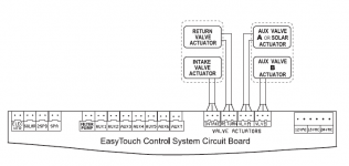
The Aux Valve A connector should connect directly to the solar valve actuator. Then you must program the ET to know that connector controls solar.
actuators.png
 
Hi - I've got a Pentair EasyTouch panel. I just self-installed a rooftop solar heating panel array. I have a 3-way Jandy valve to handle panel on-off flow.

I have a 24 VAC Goldline valve actuator from another project. I assumed the Easytouch built-in solar valve controller would send the necessary control signals for the Goldline (24 VAC switched on 3 wires), but when I inspected the EasyTouch system, I see that there's a small relay that clicks when solar is enabled/disabled but there's no voltage on the any of the 3 EasyTouch solar connector pins (Valve A). And the pins seem a bit small to handle the AC current that an actuator would require, but I might be wrong on that...

So how does a Pentair actuator valve connect to the EasyTouch panel? Does it derive 24 VAC elsewhere and just use the relay as a signal to operate the valve? I know electronics well enough to use the relay as a controller for some external circuitry I'd have to build for the Goldline actuator, but I was hoping the Pentair would provide the simple switched AC necessary, rather than me having to add additional circuitry.

I can't find a schematic for the actual operation of the EasyTouch-to-Pentair actuator circuit...can anybody advise how the EasyTouch does it with a Pentair actuator and suggest a means to do that with a third-party actuator (my Goldline)?

Thanks...
All standard valve actuators (not IntelliValve) will work with any brand of automation
 
OK, that's how I thought it should work. But I'm not getting 24VAC on any of the three pins.

Here's what I programmed on the EasyTouch:

HEAT -> POOL (Temp/Src)-> Set Temp: 100F Heat: Solar
SETTINGS -> VALVES -> SET VALVES
A: [USED SOLAR]
B: [NONE]
SETTINGS -> SOLAR
Enable: Yes
Heat Pump: No
Freeze Enbl: No
Night Cool: No
Temperature Diff
Start: 6 degrees
Run 3 degrees

Am I missing a setting to get 24VAC to appear on the 3-pin connector?

Thanks...
Plug the actuator into a known-good socket (intake or return). Try moving the 3-way switch to a different position. If the actuator moves it is good. If not, it is bad. Be sure all the micro breakers (top right corner) are reset if tripped.
 
Plug the actuator into a known-good socket (intake or return). Try moving the 3-way switch to a different position. If the actuator moves it is good. If not, it is bad. Be sure all the micro breakers (top right corner) are reset if tripped.
Good idea. I assume from your suggestion I should be able to measure 24VAC between two of the pins on the connector. Do they all have similar pinouts?
 
Good idea. I assume from your suggestion I should be able to measure 24VAC between two of the pins on the connector. Do they all have similar pinouts?
Best not to try to measure the voltage. One poster here just recently did that and shorted his board, apparently. Just use a known good socket and a known actuator and the one you are testing.
 
Chico,

The voltage for valves is always there on one of the two 'hot' pins.. The EasyTouch just closes a small relay to switch the voltage from one hot pin to the other. If none of the pins on the A (Solar) valve has 24 VAC then it is not the programming.

Keep in mind you don't measure to ground. You measure between the common pin on the connector and the hot pin.

Thanks,

Jim R.
 
Best not to try to measure the voltage. One poster here just recently did that and shorted his board, apparently. Just use a known good socket and a known actuator and the one you are testing.
Yeah, I've blown a few expensive boards before. Good way to feel really stupid! But I've got a 3-pin connector with loose wires that I can use to protect against stupidity a little bit while measuring...:rolleyes:

Chico,

The voltage for valves is always there on one of the two 'hot' pins.. The EasyTouch just closes a small relay to switch the voltage from one hot pin to the other. If none of the pins on the A (Solar) valve has 24 VAC then it is not the programming.

Keep in mind you don't measure to ground. You measure between the common pin on the connector and the hot pin.

Thanks,

Jim R.
Yeah, that's exactly how I expected it would work. When it didn't I figured I must be missing something, hence my post here.

But there's no voltage between any of the pins...or I should say, nothing more than millivolts. And the millivolt values do change when I activate/deactivate solar. So looks like something is broken in there...

I'll take a look at the other connectors, see if it's the voltage source or just that part of the circuit. Maybe the low voltage circuit breaker is bad...

I'm guessing there's no schematic for these boards, or that part of the circuit...?

I've got an old solar controller sitting around, but I kind of hate not being able to use the EasyTouch, which is already sitting there...
 

Enjoying this content?

Support TFP with a donation.

Give Support
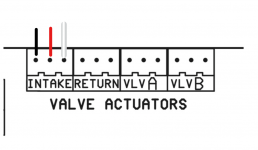
Black - Common

Red - Switch Leg

White - Switch Leg

Note that the voltage is AC, not DC.

You should measure 24 volts AC from black to red or black to white when the valve is off.

When the valve is on, the voltage switches from red to white or white to red.

So, if you had 24 volts AC from red to black with the valve off, the voltage should be 24 volts AC from white to black when the valve is on.
1685159649575.png
1685159732634.png
 
  • Like
Reactions: Jimrahbe
I'd want to know if the other valves drivers have voltage? Is it just a problem with just the A valve driver, or is the problem with all the valve drivers?
Just went out and checked. The three other valve drivers (intake, return and B Valve) indeed have 29VAC (no load) across left and middle pins. So the AC source transformer appears to be ok.

But there's high impedance on all the pins of A valve...I get varying AC values that change significantly when I touch the pins with a finger, so I'm probably just measuring AC noise there (likely no connection to the transformer on the relay common pin).

Have any of you guys seen this before? I'm thinking there's a burned trace or the relay is bad, but I'm open to other opinions. I'll have to remove the board and inspect, see what's going on there.

Am I correct in my reading of the documentation that only A valve can be used with solar? I couldn't use the B valve instead of the A valve?

btw thanks for all the responses so far. Very helpful in understand how this setup should work....
 
Found it.

I traced out the circuit board, all looked ok. Definitely appeared to be a bad relay. But I was hesitant to unsolder and replace the relay in fear of lifting or damaging the traces, some of which run under the relay bodies. That could get ugly.

I noticed a lot of crusted solder flux on the solder connections on that portion of the board, and my multimeter didn't always get a good connection when placed directly on the solder points. On the off-chance that there might be a bad solder connection to the relay pins, I re-soldered all the connections with some good leaded solder.

That was it, one or more bad solder connections to the relay and/or the connector. All working fine now.

Thanks to all for the assistance for explaining out how it was supposed to work. That helped a lot in the debug process.
 
Chico.

Great job!!! :goodjob:

I used to work as a Radar Tech on the F4E.. That is the F4 with the gun in the nose, right behind and below the Radar System.

Early on, after firing the gun, the number one repair was "re-soldered connections on Printed Circuit Card" Some of the modules and relays were only attached by a few solder joints. The components were heavy enough, that when the gun fired, the vibration would crack the solder joints around the pins. Some actually fell completely off.

Thanks for the old memories..

I love the smell of JP4 in the mornings... :mrgreen:

Jim R.
 
  • Like
Reactions: JamesW
Chico.

Great job!!! :goodjob:

I used to work as a Radar Tech on the F4E.. That is the F4 with the gun in the nose, right behind and below the Radar System.

Early on, after firing the gun, the number one repair was "re-soldered connections on Printed Circuit Card" Some of the modules and relays were only attached by a few solder joints. The components were heavy enough, that when the gun fired, the vibration would crack the solder joints around the pins. Some actually fell completely off.

Thanks for the old memories..

I love the smell of JP4 in the mornings... :mrgreen:

Jim R.

Great story!

Yikes. Not the best QC on stuff intended to keep the a human being alive. Worst case scenario pretty grim.

OTOH, the QC on the Pentair board appears pretty bad too. But worst case for Pentair is they get to overcharge for another board (unless the user is geeky enough to fix it himself :rolleyes: ) ....


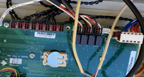
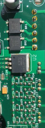
Pictures?

Crusty old flux on a lot connections.

Probably caused connection issues between the traces and the relay and/or connector pins.

Hitting all the connections with an iron and solder made it all work again.

Sorry, no pix after cleanup.


IMG_8146.JPG
 
  • Like
Reactions: Scottchbright
Thread Status
Hello , This thread has been inactive for over 60 days. New postings here are unlikely to be seen or responded to by other members. For better visibility, consider Starting A New Thread.