how to use my own power supply for Aquarite Salt Cell

flpoolgeek

In The Industry
Nov 2, 2017
15
Bradenton FL
Hi Guys!

I'm trying to avoid the cost of buying the Aquarite Controller box to power my T-15 Cell.

I read in another thread that you can power the Pentair IC40 using a 36v 10a power supply and I want to do the same. I'm just not what voltage to power the T-15 cell with.

According to inyopools.com (http://www.inyopools.com/HowToPage/h...-values.aspx):

"...CELL VOLTAGE - The Cell Voltage is typically 22.0 to 25.0 Volts when chlorine is being generated, otherwise it is 30 to 35 Volts."

and

"...CELL AMPERAGE - The cell's average amperage when chlorine is being generated varies with the size of cell installed: T-15 is 3.1 to 8.0 amps; T-9 is 2.3 to 6.7 amps; T-5 is 1.9 to 5.7 amps; and t-3 is 1.3 to 4.5 amps. When the cell is not generating chlorine the amperage is 0"


I do realize that without a controller, the salt cell will always be generating but I intend to use a different controller (Arduino controller) with a relay to handle the powering on/off of the salt cell.

My question is what power supply should do the trick? The same as the one you guys mentioned for the Pentair IC40?

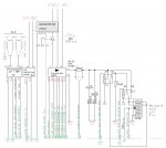
I believe that the Aquarite T-15 Cell has 5 connections in the cable that runs to the controller. Does anybody know which pins are for what?


I really do appreciate any direction you could give me on this. Thanks! :smile:
 
Holding the plug vertically with the cord going down and looking at the connection points. 1 is top left, 2 is top right, 3 is second down left and so on with 9 being lower left and 10 being lower right.

1) Black - Power to cell
2) White - Power to cell
3) Black - Power to cell
4) White - Power to cell
5) Brown - Not used
6) Red - Goes to thermistor
7) Orange - Not used
8) Yellow - Not used
9) Green - Not used
10) Blue - Goes to thermistor.

A power supply that has 24 to 30 volts dc and 10 amp capacity should work.

I can't recommend that you do this as there are safety issues related to making your own supply. Make sure that you have a flow switch incorporated to prevent generating with no flow.

Extend AquaRite T-Cell Cable
 
I would think if you made your own power supply and didn't use the controller you wouldn't be able to adjust the output either so it may or may not work right. Benefit to adjusting the output is you can set the output lower to extend the life of the cell instead of running it at 100% all the time. I personally run my Jandy Pro TruClear at 80%. I run the pump a little longer but it will last longer without maxing out the cell at 100%

Not to mention the safety concerns....
 
The OP is setting an example to the Pentair salt cell with a built-in controller in whole or in part (correct me if I'm wrong) vs Hayward T-15 that has nothing but an array of titanium plates coated with either ruthenium or iridium and a thermostat. The voltage supply to the T-15 is fixed ranging from 24-26 Vdc when chlorinating and the output % settings dictate the amount of time the cell should remain powered on based on the preset 180 mins cycle.

There's a wealth of knowledge in the below threads for those who wish to expand their knowledge about the salt cell.

http://www.troublefreepool.com/threads/100791-What-makes-the-difference

http://www.troublefreepool.com/threads/95581-Economics-of-Saltwater-Chlorine-Generators

http://www.philipdoolittle.com/2018/03/salt-cell-failure-post-mortem-with.html
 
Hi Everybody,

JamesW, Meadow, and Jwmote, thanks for all your help!

With the info you guys have given me and a lot of thought, I've decided that I'm going to do this, do it right and do it safely.

Below is a little bit more detail on how I plan on setting this up. Your feedback/suggestions/advice are EXTREMELY useful to me so please contribute any Jedi wisdom you may have!

A few people have voiced safety concerns and I would also appreciate if you could point out any safety hazards I may be overlooking.

I am going to be adding a 120v 50a breaker to my existing pool equipment subpanel. That breaker will feed power to 2 circuits:

Circuit 1. Will go to a 120vac to 9vdc adapter which will power my Arduino controller board.

Circuit 2. Will go to a 120vac to 24vdc adapter which will power a my Aquarite T-cell 15.

The Arduino controller board on Circuit 1 will have a relay which will control power to Circuit 2 (salt cell). This will allow me to control how long the cell is powered/generating. There will also be an h-bridge incorporated to reverse polarity to the cell. I have my own flow rate sensor which will be connected to the Arduino and will only power the cell if there's flow.

All of this will be in a non-metal weatherproof enclosure on the wall near the pool equipment. The electric wires will be properly run with conduit tubing.

Some questions:

1. According to inyoupools.com, "The Cell Voltage is typically 22.0 to 25.0 Volts when chlorine is being generated, otherwise it is 30 to 35 Volts". That's confusing to me. Wouldn't the cell voltage be 0 (no power) when it is not generating? Could the 30-35v they are referring to be the voltage of the entire aquarite system (aquarite controller included)?

2. Voltage supplied to cell. The cell voltage is typically 22-25v when generating chlorine. I'm assuming the variance is because the cells of different size have a different resistance. I'm also assuming that, AS LONG AS THE VOLTAGE IS SOMEHWERE NEAR THE RANGE (maybe 21-26v), the voltage sent into the cell doesn't make much of a practical difference with regard to performance and longevity. Do you feel this is a good assumption or could I screw something up with a volatage that is 1 or 2 volts out of the 22-25v range?

3. Getting temperature reading. I opened up an old cell I had and I noticed a plastic probe-like thing near to where the plates are connected in the cell. I'm assuming this is the probe which measures temperature. I'm assuming there's a thermistor inside that and the wires go to the controller which reads the resisteace and estimates the temperature. Is that how this works? I'm confused because last year I had to repair another aquarite controller and all I did was replace the SL32 2R025 thermistor and it worked. But that begs the question, why is the thermistor in the controller and not in the cell? I must be misunderstanding how this works. If you can offer any insight, please do :)

4. Getting salt readings. Once I have figured out how to get the temperature, the last thing I have to figure out is how to calculate the salt readings like the aquarite does. I found this thread (https://www.troublefreepool.com/threads/114565-How-salt-systems-determine-salinity) which discusses how the aquarite determines the salinity. But I'm still not sure how I would go about doing that myself with my own controller. I'm pretty sure I can figure out a way to get the real-time voltage and amperage of the salt cell circuit. Probably using an ardunio current sensor. With voltage, amperage and temperature, I should be able to calculate the conductivity, correct? I am going to dig further into this but any advice you can give me would be very much appreciated.

5. Finally, any safety hazards I may be overlooking?

Again, I REALLY appreciate your advice with this project.

I will update this thread as I build it.

And if know of any members who may not have seen this thread but would have a lot to contribute, could you please invite them to this thread or let me know so I can invite them?

Thanks Everybody!
 
The voltage for the aquarite is measured before the relay. So, you get a reading with the cell powered or not powered. When powered, you get a voltage drop based on the amperage. The more current the cell uses, the more the voltage drops. You should make sure that the power supply can maintain 24 volts under load.

The thermistor in the cell measures temperature. The thermistor in the box acts as a surge suppressor. Two different thermistors for different purposes.

You don't really need to measure salinity or temperature. Just get a K-1766 and maintain the salinity at about 3,200 ppm.

Get a flow switch to make sure that the cell is not powered with no flow.
 
Hi James,

Great info. I will get the power supply and adjust the pot so that voltage is between 30-35v. I guess the voltage will then drop to what it needs to be based on the amperage of the cell.

Yes, I do have a flow rate sensor incorporated into the plan. I'm using a flow rate sensor vs a flow switch because I will be installing this in conjunction with a acid feeder and ph sensor. I'm already using it for that part of the system so I might as well use the same flow rate reading in place of a flow switch. I do have one more obstacle to overcome with the acid sense/dispense system. I need to find a solenoid that won't corrode with the acid. I'm having trouble finding one of those. There are $5-$10 solenoids which would be perfect if not for the fact that they have stainless steel plungers which may not hold up well to the acid. I will post in a new thread for that but if you have any ideas, I'm all ears!

Thanks :)
 
The thermistor in the cell measures temperature. The thermistor in the box acts as a surge suppressor. Two different thermistors for different purposes.

You don't really need to measure salinity or temperature.

I am watching the thread with interest, not only because I've always thought the Aquarite was overly complicated for what it does, and at the same time it's somewhat failure prone in its current form... not to mention the fact that the cells are crazy expensive and non-field repairable - they should be neither.

You mentioned the temperature sensing thermistor in the cell and I am just guessing its only purpose is to identify when the pool is below a cut-off temp (60F I read somewhere here I think). I don't know if it plays into the generate/off cycle as the water gets colder... probably not. However it may be taking temp into the calculation (with voltage/current) to come up with salt readings.

If low temp cut-off is its only purpose you might not really need it, potentially using another method for winter season cut-off. But since it cuts off on low/high salt, I would say temp has to factor in into the salt level estimation.

The other note on the temperature thermistor, it is important to understand that there are a lot of different specs and response curves on temp thermistors and I have never seen the spec on the one in the T-15 cell. It is pretty common in pool equipment to see the 10K NTC thermistor (The resistance in 25 °C is 10K +- 1%) but that is merely a guess. Put a vom on the two sensor lines when the temp is around 77F and see what it reads.

I know the temp sensors (PSC2023 and PSC2022) on my old Hayward Pool Boss system are not 10K thermistors and remain to this day an unknown spec, and are unobtainium so far, but that is another matter. So far, even though they are not available anymore, Hayward has refused to cough-up the spec on the PSC2023 and PSC2022 sensors so they could be sourced from the likes of digikey, and I doubt they'll disclose the thermistor specs in the cell. These failing sensors most likely are the cause of a lot of trashed but otherwise good Pool Boss systems.

Good luck on your replacement.
 

Enjoying this content?

Support TFP with a donation.

Give Support
Hi Guys!

I've been working on another project for the past few months so just getting back to this project. I'm about to test my power supply with my aquarite cell. My dog did me a favor by chewing threw the cord of the cell. Now I don't have to cut it.

I see the power wires (2 black and 2 white) which I have to hookup to my power supply. I was just going to hook those up in parallel to my PSU (2 black to positive terminal and 2 white to negative terminal) but then I had the thought that maybe the wiring may not be as I'm assuming.

JamesW (or anybody that knows), is my assumption correct that the 2 white wires should go to one polarity on my PSU while to two black should go to the other polarity?

I just want to make sure. I will then try it out tomorrow and post back here to update you guys

Thanks!
Johnny
 
Update:

I used a t-cell cleaning stand and a t-3 cell filled with a 3000ppm salt solution I hooked up my power supply and plugged it on. It immediately started generating chlorine. Faster than I expected.

I tested voltage and saw that my power supply was actually outputting 70v! So I adjusted the pot down to 36v. It wouldn't go lower than that which I believe is too high for the cell which should get 22 to 25v.

The power supply I had bought was a 36v with adjustable pot but apparently you can only adjust the voltage up, not down. So I ordered a 24v power supply instead and that should arrive shortly.

But just wanted to post an update to let you guys know that it did indeed work!
 
HI Guys,

I know it's been a while since I last posted here but I got sidetracked with other projects.

The project is still on and would love your help with making sure I'm on the right track here towards the homestrech.

Ok, as mentioned before, I am incorporating the flow switch to turn off power when no flow is detected and I'm also incorporating polarity reversing. So we're good there.

But I came across something unexpected that I'm confused about...

According to How to Read and Adjust the Hayward Aqua Rite SCG Operational Values - INYOPools.com

"...CELL VOLTAGE - The Cell Voltage is typically 22.0 to 25.0 Volts when chlorine is being generated...." and "...CELL AMPERAGE - The cell's average amperage when chlorine is being generated varies with the size of cell installed: T-15 is 3.1 to 8.0 amps; T-9 is 2.3 to 6.7 amps; T-5 is 1.9 to 5.7 amps; and t-3 is 1.3 to 4.5 amps. When the cell is not generating chlorine the amperage is 0"

If the supply voltage is about the same at around 24v, and the amperage through the cell is determined by its resistance (current = voltage divided by resistance), then why the heck does the smaller cell (which has less blades and therefore should have less resistance) get lower amperage?

I would think that if, for example, it had double the plates, the resistance would double and therefore drop the current by half.

I think I may be missing something or misunderstanding something somewhere. I want to make sure I'm understanding this right so that I can make the system so I can just plug in any size t-cell without having to worry about adjusting voltage or resistance.

Any help you could give me would be very much appreciated!

Johnny the PoolGeek
 
here are PROS and CONS on your development:
1. you need to know how to read pH and REDOX parameters, then those convert to salinity ppm. But even better to have conversion table to achieve proper water balance by saturation index Si, which relates to calcium and alkalinity in the water (pH, temperature, calcium hardness, and total alkalinity)
2. Salinity adjustment you can adapt in the PLC by learning curve over the time, when you know how much Amps current is required to balance water vs time.
3. You need current source power supply with voltage stabilization. Some linear stabilization can use as voltage or current source. Then you design current limitation for different switching steps. (on the market is hard to find such a power source to voltage level 30 - 33 VDC).

All others to make is kind of easy with PLC programming.
But above issues hinder me to finalized my home PLC pool control. Its painful to pay 1500 eur for market product with island controller, since you have already one house PLC for everything...
Probes pH+REDOX, transducer, MCB, pH pump, power supply and relays cost around 600 eurs.
Wish somebody could help more ;) In my pool i want to use Loxone system.
 

Attachments

  • salt and pH regulation scheme.JPG
    salt and pH regulation scheme.JPG
    87.6 KB · Views: 19

Enjoying this content?

Support TFP with a donation.

Give Support
Thread Status
Hello , This thread has been inactive for over 60 days. New postings here are unlikely to be seen or responded to by other members. For better visibility, consider Starting A New Thread.