In December, I finally implemented a system I'd been planing off and on since planning our pool build 2 years prior.
When we built our pool, the pool builder offered an Intelletouch automation system. I didn't feel it was worth the asking price, and found it lacking in a couple of key features. First, and most important to me, was although it offered mobile phone control, it used (or at least from what I could find online) a proprietary communication system, so I couldn't tie it into my home automation system for smart control (integrated control of other systems, not just remote control). I was already using Home Assistant, which is one of the more advanced home automation systems available - and free, so integrating it, was a key feature I was after. Also, it provided no valve position feedback, so if a valve actuator failed, and I was pumping my spa down, I'd have no way to know.
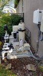
What we started with, was a Pentair Superflow VS pump running on its own timers, a manually controlled Pentair gas heater and an Intellechlor running on a mechanical timer in a Pentair load center, with manual valves. Features I looked for on the heater and pump were that they were both capable of digital control via dry contact connections - basically that they could be remotely controlled by the simple turning on and off of a switch, rather than some possibly proprietary command protocol.
After a year of operating and making notes of control goals as I went, my grand plans of what I wanted to do got a lot simpler. For the most part, the only thing that wasn't "set it and forget it" for my pool control over that year was switching between pool and spa operation (switching the position of drain and return manifold valves, turning on the pump and heater) or setting the pump to quick clean for vacuuming. I only changed pump timer values once during the year, and Intellichlor setting 3 or 4 times over the year. So I could do full pump control in my home automation system, it would only be for wow factor, and not really change anything for me.
Pool lights are switched in the house, so I'd already taken control of them with a Z-Wave light switch early on, with an automation in Home Assistant that will pulse the power to set colors as chosen in a drop down menu.
What it came down to for automation was needing to control 4 relays to operate 2 valve actuators in 2 directions, a relay to call the heater, and a relay to tell the Superflow to run at its "Quick Clean" speed setting. I also wanted to monitor temperature and pressure in the filter, so I could get alerts when the spa was warmed up, and if backpressure in the filter indicated it was time to clean.
My platform of choice for control was a NodeMCU (ESP8266 based dev board) because it's cheap, is programmable in the Arduino IDE and has wifi built in for cheap isolated networking (I would not be comfortable tying outside hardware into my house's Ethernet network via copper - we only use optic fiber for that at work due to lightning damage risk and that would add far more cost than I want).
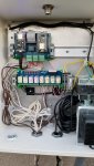
The NodeMCU only has one analog input, and didn't have enough digital I/O to switch it between my pressure (generic, picked up on e-bay) and temperature (Pentair - paid through the nose for what it is, but it's in a very nice package to just strap onto the pipe) sensors. I'd started to consider what I'd need to add, then realized that since NodeMCU boards are only $3.50 a pop, it was cheaper and less hassle to just use two, and have them talk to each other as needed. A generic 8 relay board built for using with Arduinos was a quick grab on eBay (leaving me with a couple spare auxiliary relays for future expansion), then I started looking for enclosures... Sprinkler enclosures to start with, until my manager told me he'd just keep an eye out for an enclosure on the scrap pile (I work for an industrial control company) and a couple weeks later I got a nice sized lightning damaged enclosure with a backplane and some salvageable terminal and din-rail hardware. With a fair amount of scrubbing, some fresh paint, and most of its hardware going in the trash, it still smells faintly enough like smoke to make me hunger for roasted marshmallows, but it will do for home use.
I originally planned to build the circuit on perf board, soldering jumpers on the back for all the connections, but a friend turned my on to a PCB fabricator in China that does low volume production. Since it was a no-rush project, why not go a little further to look better? My first draft schematic was in Adobe Illustrator. I tried DesignSpark PCB (free cad software), and in a fraction of the time, had a better schematic that was much easier to edit. From there DesignSpark automatically designed a 2 layer PCB layout, that I ended up re-working quite a bit for better placement, allowing for a smaller board, and fattening up main power and ground bus lines. It was my first go at designing a printed circuit board, and it was far smoother and easier than I'd expected it would be. It also meant I could put some circuit board art in and feature Eddie Murphy as James Brown singing about my hot tub. Forty eight bucks and 5 days later I had 5 circuit boards (minimum order) in my hands.
I only needed one board but that was minimum order and it was good that I had spares. I "wisely" soldered all the components on the board straight away before discovering that the sockets I'd bought were for round hole pins and wouldn't accept the NodeMCU boards. Larger sockets, and the second board was the one that went into service. I also, unsurprisingly, discovered that since I hadn't built up the whole circuit on a breadboard and tested it first, some of the individual circuits that tested out fine on the breadboard ran into problems if they were in use when the NodeMCU booted, or had issues with cross-talk. So... there are some cut traces and jumpers on the board, but even folks I know who do board design for a living usually find stuff to fix on their first revision, so I won't feel bad for that. A little 3D printer magic later, I had mounting hardware to DIN rail mount the circuit boards.
Writing, testing and debugging software spread over a couple of days. Telemetry and commands communicated between the controller to Home Assistant via the MQTT protocol over WiFi. After picking up a pair of Intermatic valve actuators, installation of the box and electrical one afternoon, the valves, control circuits, and analog sensors another, at which point the system worked - as long as I manually flipped the switches I'd wired up to simulate valve position. The next afternoon I added waterproof magnetic reed switches on the valve actuators to give position feedback and it's been doing its thing since, aside from pressure feedback.
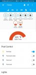
The pressure value is not changing when the pressure changes, though it did on my test bench. I haven't jumped on debugging that yet, since I care far more about temperature, but I still do like the idea of getting an alert if the pressure goes high, or fails to change daily, indicating the pump did't run through it's timed cycle. I'll get to it eventually, but the important part is there - I can say "Alexa, turn on the Pool Spa" and some 20-30 minutes later, the lights above the kitchen counter start dancing in a rainbow animation to let me know the spa has hit 100 degrees. More importantly, when my wife and I get out of the hot tub, I don't have to walk around the side of the house in the dark and sometimes cold and rain to fumble with valves and buttons when we are done.
Future work includes getting the pressure reading functional and adding control for the spa blower. If I can find a drop in Z-Wave or Wifi switch that will handle that load, that will be a quick and easy answer, but I suspect it may be a solid state relay going in the load center switched by one of my two auxiliary relays. That route has more circuit isolation hurdles to jump.
For anyone else looking to control a a Maxflow VS - Pentair sells a cable to do dry contact control, but at $50 retail, that's a $15 connector with what seems like less than $35 worth of wire connected to it. The connector is a Switchcraft EN3C8FX round female connector. The Superflow manual explains how to use it for dry contact or +5v control, but they don't give the pinouts of the connector - only the color code of the $35 piece of wire they sell with the connector. I probed the connector with a voltmeter, and then a resistor (to avoid a straight up short of power to ground) and found the following pinout.
Facing the pump (looking into the male connector in the pump, or the back of the female connector) numbering the pins clockwise starting at the first pin after the registration notch:
Pin 1 - Quick Clean
Pin 2 - Stage 3
Pin 3 - Stage 2
Pin 4 - Stage 1
Pin 6 - Gnd (-5v potential from pin 7, +3v to others)
Pin 8 - +5VDC (+5 potential to pin 6, +8 to others)
When we built our pool, the pool builder offered an Intelletouch automation system. I didn't feel it was worth the asking price, and found it lacking in a couple of key features. First, and most important to me, was although it offered mobile phone control, it used (or at least from what I could find online) a proprietary communication system, so I couldn't tie it into my home automation system for smart control (integrated control of other systems, not just remote control). I was already using Home Assistant, which is one of the more advanced home automation systems available - and free, so integrating it, was a key feature I was after. Also, it provided no valve position feedback, so if a valve actuator failed, and I was pumping my spa down, I'd have no way to know.
What we started with, was a Pentair Superflow VS pump running on its own timers, a manually controlled Pentair gas heater and an Intellechlor running on a mechanical timer in a Pentair load center, with manual valves. Features I looked for on the heater and pump were that they were both capable of digital control via dry contact connections - basically that they could be remotely controlled by the simple turning on and off of a switch, rather than some possibly proprietary command protocol.
After a year of operating and making notes of control goals as I went, my grand plans of what I wanted to do got a lot simpler. For the most part, the only thing that wasn't "set it and forget it" for my pool control over that year was switching between pool and spa operation (switching the position of drain and return manifold valves, turning on the pump and heater) or setting the pump to quick clean for vacuuming. I only changed pump timer values once during the year, and Intellichlor setting 3 or 4 times over the year. So I could do full pump control in my home automation system, it would only be for wow factor, and not really change anything for me.
Pool lights are switched in the house, so I'd already taken control of them with a Z-Wave light switch early on, with an automation in Home Assistant that will pulse the power to set colors as chosen in a drop down menu.
What it came down to for automation was needing to control 4 relays to operate 2 valve actuators in 2 directions, a relay to call the heater, and a relay to tell the Superflow to run at its "Quick Clean" speed setting. I also wanted to monitor temperature and pressure in the filter, so I could get alerts when the spa was warmed up, and if backpressure in the filter indicated it was time to clean.
My platform of choice for control was a NodeMCU (ESP8266 based dev board) because it's cheap, is programmable in the Arduino IDE and has wifi built in for cheap isolated networking (I would not be comfortable tying outside hardware into my house's Ethernet network via copper - we only use optic fiber for that at work due to lightning damage risk and that would add far more cost than I want).
The NodeMCU only has one analog input, and didn't have enough digital I/O to switch it between my pressure (generic, picked up on e-bay) and temperature (Pentair - paid through the nose for what it is, but it's in a very nice package to just strap onto the pipe) sensors. I'd started to consider what I'd need to add, then realized that since NodeMCU boards are only $3.50 a pop, it was cheaper and less hassle to just use two, and have them talk to each other as needed. A generic 8 relay board built for using with Arduinos was a quick grab on eBay (leaving me with a couple spare auxiliary relays for future expansion), then I started looking for enclosures... Sprinkler enclosures to start with, until my manager told me he'd just keep an eye out for an enclosure on the scrap pile (I work for an industrial control company) and a couple weeks later I got a nice sized lightning damaged enclosure with a backplane and some salvageable terminal and din-rail hardware. With a fair amount of scrubbing, some fresh paint, and most of its hardware going in the trash, it still smells faintly enough like smoke to make me hunger for roasted marshmallows, but it will do for home use.
I originally planned to build the circuit on perf board, soldering jumpers on the back for all the connections, but a friend turned my on to a PCB fabricator in China that does low volume production. Since it was a no-rush project, why not go a little further to look better? My first draft schematic was in Adobe Illustrator. I tried DesignSpark PCB (free cad software), and in a fraction of the time, had a better schematic that was much easier to edit. From there DesignSpark automatically designed a 2 layer PCB layout, that I ended up re-working quite a bit for better placement, allowing for a smaller board, and fattening up main power and ground bus lines. It was my first go at designing a printed circuit board, and it was far smoother and easier than I'd expected it would be. It also meant I could put some circuit board art in and feature Eddie Murphy as James Brown singing about my hot tub. Forty eight bucks and 5 days later I had 5 circuit boards (minimum order) in my hands.
I only needed one board but that was minimum order and it was good that I had spares. I "wisely" soldered all the components on the board straight away before discovering that the sockets I'd bought were for round hole pins and wouldn't accept the NodeMCU boards. Larger sockets, and the second board was the one that went into service. I also, unsurprisingly, discovered that since I hadn't built up the whole circuit on a breadboard and tested it first, some of the individual circuits that tested out fine on the breadboard ran into problems if they were in use when the NodeMCU booted, or had issues with cross-talk. So... there are some cut traces and jumpers on the board, but even folks I know who do board design for a living usually find stuff to fix on their first revision, so I won't feel bad for that. A little 3D printer magic later, I had mounting hardware to DIN rail mount the circuit boards.
Writing, testing and debugging software spread over a couple of days. Telemetry and commands communicated between the controller to Home Assistant via the MQTT protocol over WiFi. After picking up a pair of Intermatic valve actuators, installation of the box and electrical one afternoon, the valves, control circuits, and analog sensors another, at which point the system worked - as long as I manually flipped the switches I'd wired up to simulate valve position. The next afternoon I added waterproof magnetic reed switches on the valve actuators to give position feedback and it's been doing its thing since, aside from pressure feedback.
The pressure value is not changing when the pressure changes, though it did on my test bench. I haven't jumped on debugging that yet, since I care far more about temperature, but I still do like the idea of getting an alert if the pressure goes high, or fails to change daily, indicating the pump did't run through it's timed cycle. I'll get to it eventually, but the important part is there - I can say "Alexa, turn on the Pool Spa" and some 20-30 minutes later, the lights above the kitchen counter start dancing in a rainbow animation to let me know the spa has hit 100 degrees. More importantly, when my wife and I get out of the hot tub, I don't have to walk around the side of the house in the dark and sometimes cold and rain to fumble with valves and buttons when we are done.
Future work includes getting the pressure reading functional and adding control for the spa blower. If I can find a drop in Z-Wave or Wifi switch that will handle that load, that will be a quick and easy answer, but I suspect it may be a solid state relay going in the load center switched by one of my two auxiliary relays. That route has more circuit isolation hurdles to jump.
For anyone else looking to control a a Maxflow VS - Pentair sells a cable to do dry contact control, but at $50 retail, that's a $15 connector with what seems like less than $35 worth of wire connected to it. The connector is a Switchcraft EN3C8FX round female connector. The Superflow manual explains how to use it for dry contact or +5v control, but they don't give the pinouts of the connector - only the color code of the $35 piece of wire they sell with the connector. I probed the connector with a voltmeter, and then a resistor (to avoid a straight up short of power to ground) and found the following pinout.
Facing the pump (looking into the male connector in the pump, or the back of the female connector) numbering the pins clockwise starting at the first pin after the registration notch:
Pin 1 - Quick Clean
Pin 2 - Stage 3
Pin 3 - Stage 2
Pin 4 - Stage 1
Pin 6 - Gnd (-5v potential from pin 7, +3v to others)
Pin 8 - +5VDC (+5 potential to pin 6, +8 to others)