Help Wiring New Pump

rbrown226

Member
Mar 16, 2021
6
Coconut Creek, FL
I am replacing my Hayward dual speed pump with a Xtremepower dual speed. On the Hayward, there are four wires (Red, Black, Blue, and Green). On the new pump, there is a switch to change speeds from low to high. The wiring of the new pump has only two connections and a ground. The Hayward has three wiring connections. Am I able to wire the new pump to have my controller change the speeds instead of using the switch on the pump? If So, how do I wire that? If it is not possible, how do I wire the new pump with only two terminals?

Thank you!
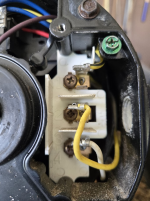
What are you using now to control 2 speeds? Show a picture of the new motor with the wiring compartment open.
 
Looks like the pump speed can only be set by the switch on the pump. To power your new pump it just needs two hot wires (250V between them) and a ground. Not sure what your current controller is, but I would bet if you looked for the install manual for it there would be instructions on connecting it to a single speed 250V pump.
Xtremepower Manual
Can I just bypass the switch and wire it directly to the area I circled?
1746557682057.png
 
Can I just bypass the switch and wire it directly to the area I circled?
View attachment 643498
Yes. Hard to read, but it looks like the terminal top right is high speed (circuit 1 on the Intermatic) and the top left is low (circuit 2 on the Intermatic). If it is reversed, just move the wires.
The "common" appears to be the center terminal of that board. It would normally be the wire that goes to the A terminal on a Century 2-speed pump motor, which is what you probably have now.
You won't need to use the terminals that the diagram shows for the "line" wires except for the ground terminal.
A picture of the timer with the insulator removed would help determine which wire is going to the common from the timer.
I just posted it!
 
Image from the pump manual might make it easier to figure out.

This is a half guess (can't follow the wires in the intermatic timers), but I would stay Black and Red should be on the outside terminals and blue is on the middle (common). Left is low and right is high.

If you have a meter, check to see which wires have voltage when it on low and high and which wire has voltage to ground in both cases. That would tell you what is common and which is high and low.

1746562758774.png
 

Enjoying this content?

Support TFP with a donation.

Give Support