Hey, I have found this subject on the interwebs in a few different place...
Links deleted by Jim R. (New poster)
However I haven't been able to find anywhere where someone was able to break down the communication protocol between the drive control module and the controller itself. I have been able to identify a couple more pieces of information than what was posted on the above sites, which I will describe below, and also summarize what I have found from those sites.
For reference, I have the Super Pump VS 700.
Doing my own sniffing of the RS485, I got basically the same data as previously posted.
The command strings I can tell you how it breaks down..
01 01 58 02 C1 0D 0A
01 = Address of the device
01 = Command
58 02 = INT16 Little Endian. For the non-programmers little endian means the significant byte comes last, so you have to flip the bytes to get 02 58. Convert that hex value to decimal and you 600...which is the RPM value
C1 = Checksum, this is used for error detection in the byte string
0D = Carriage Return
0A = End of Line
The last 2 bytes are pretty standard in most communication, to let the device know to stop reading and process the previous bytes.
What I am stuck on, is how is the checksum generated? I can't figure out what algorithm is used.
I did notice on one of the previously posted sites they sniffed this string for the same RPM.
01 01 58 22 21 0D 0A
Notice it has 58 22, where the extra 2 in 22 seems to be ignored. I tested my newer pump, and it accepts both strings to set the same RPM. There are several other strings with the same issue in the 600-900 RPM range.
There does seem to be a pattern, where the 2 changes to a 0, the checksum byte only changes the first digit. In all the checksums the 2nd digit remains the same. I feel like it may be significant, but I can't figure out why or how it matters.
Also, there is a reply message from the pump motor controller. When you send the above message you will get this type of reply:
01 40 00 00 00 00 00 00 00 17 00 00 00 57 02 c7 0d 0a
I have no idea what this part of the string is...01 40 00 00 00 00 00 00 00 17 00 00 00
But the 57 02 is what I believe to be the actual RPM. Convert that number the same way as mentioned above and you get 599. So its responding with the actual RPM the motor is turning. Sniff it for awhile and you will see 599,598,600,601, etc.
There is also 1 other command I have sniffed which looks like this...
01 07 06 4C 0D 0A
The command value changes, so I don't really know what the 06 means, but the 4c is probably another check digit followed by the standard 0D 0A.
What is important is this command remains constant no matter what RPM you set the control module to. I believe it is just a request for the Watt usage. Because the response from the pump is like this....
01 60 82 01 03 00 23 00 17 00 17 00 2c 00 00 5d 0d 0a ....Response at 650 RPM, Watt usage on screen was 35
01 60 82 01 04 00 25 00 18 00 18 00 30 00 00 80 0d 0a ....Response at 850 RPM, Watt usage on screen was 37
Notice the 7th byte in the first string is 23, which converted to decimal is 35. 2nd string is 25 which is 37 in decimal.
What the rest of all that means is a mystery.
If anyone has any ideas about some of the other bytes, or can figure out how the checksum is calculated, I would greatly appreciate it.
For anyone wanting to understand how I started sniffing this data, here are some pictures.
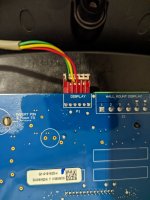
This is the back of the display module that sends RPM values, and requests data from the motor controller. The red wire is 12v power to the display, yellow and black are the communication wires, and green is the common. I believe the Wall Mount connection is the same as the display connection, just a different connector for a longer run wire to remotely mount the display.

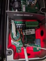
Here is the motor side controller, the wires coming in are from the display module, plus the wires I've added which go to my RS485 to USB adapter on my PC to sniff the packets. I don't see any other communication connections.

Links deleted by Jim R. (New poster)
However I haven't been able to find anywhere where someone was able to break down the communication protocol between the drive control module and the controller itself. I have been able to identify a couple more pieces of information than what was posted on the above sites, which I will describe below, and also summarize what I have found from those sites.
For reference, I have the Super Pump VS 700.
Doing my own sniffing of the RS485, I got basically the same data as previously posted.
The command strings I can tell you how it breaks down..
01 01 58 02 C1 0D 0A
01 = Address of the device
01 = Command
58 02 = INT16 Little Endian. For the non-programmers little endian means the significant byte comes last, so you have to flip the bytes to get 02 58. Convert that hex value to decimal and you 600...which is the RPM value
C1 = Checksum, this is used for error detection in the byte string
0D = Carriage Return
0A = End of Line
The last 2 bytes are pretty standard in most communication, to let the device know to stop reading and process the previous bytes.
What I am stuck on, is how is the checksum generated? I can't figure out what algorithm is used.
I did notice on one of the previously posted sites they sniffed this string for the same RPM.
01 01 58 22 21 0D 0A
Notice it has 58 22, where the extra 2 in 22 seems to be ignored. I tested my newer pump, and it accepts both strings to set the same RPM. There are several other strings with the same issue in the 600-900 RPM range.
| 01 01 58 02 C1 0D 0A | 01 01 58 22 21 0D 0A |
| 01 01 71 02 D2 0D 0A | 01 01 71 22 32 0D 0A |
| 01 01 8A 02 51 0D 0A | 01 01 8A 22 B1 0D 0A |
| 01 01 A3 02 42 0D 0A | 01 01 A3 22 A2 0D 0A |
| 01 01 BC 02 D6 0D 0A | 01 01 BC 22 36 0D 0A |
| 01 01 D5 02 9E 0D 0A | 01 01 D5 22 7E 0D 0A |
| 01 01 EE 02 F0 0D 0A | 01 01 EE 22 10 0D 0A |
There does seem to be a pattern, where the 2 changes to a 0, the checksum byte only changes the first digit. In all the checksums the 2nd digit remains the same. I feel like it may be significant, but I can't figure out why or how it matters.
Also, there is a reply message from the pump motor controller. When you send the above message you will get this type of reply:
01 40 00 00 00 00 00 00 00 17 00 00 00 57 02 c7 0d 0a
I have no idea what this part of the string is...01 40 00 00 00 00 00 00 00 17 00 00 00
But the 57 02 is what I believe to be the actual RPM. Convert that number the same way as mentioned above and you get 599. So its responding with the actual RPM the motor is turning. Sniff it for awhile and you will see 599,598,600,601, etc.
There is also 1 other command I have sniffed which looks like this...
01 07 06 4C 0D 0A
The command value changes, so I don't really know what the 06 means, but the 4c is probably another check digit followed by the standard 0D 0A.
What is important is this command remains constant no matter what RPM you set the control module to. I believe it is just a request for the Watt usage. Because the response from the pump is like this....
01 60 82 01 03 00 23 00 17 00 17 00 2c 00 00 5d 0d 0a ....Response at 650 RPM, Watt usage on screen was 35
01 60 82 01 04 00 25 00 18 00 18 00 30 00 00 80 0d 0a ....Response at 850 RPM, Watt usage on screen was 37
Notice the 7th byte in the first string is 23, which converted to decimal is 35. 2nd string is 25 which is 37 in decimal.
What the rest of all that means is a mystery.
If anyone has any ideas about some of the other bytes, or can figure out how the checksum is calculated, I would greatly appreciate it.
For anyone wanting to understand how I started sniffing this data, here are some pictures.
This is the back of the display module that sends RPM values, and requests data from the motor controller. The red wire is 12v power to the display, yellow and black are the communication wires, and green is the common. I believe the Wall Mount connection is the same as the display connection, just a different connector for a longer run wire to remotely mount the display.

Here is the motor side controller, the wires coming in are from the display module, plus the wires I've added which go to my RS485 to USB adapter on my PC to sniff the packets. I don't see any other communication connections.

Last edited:


