Hayward Super Pump 2 speed wiring to Aquaplus SWG

msickler

Member
Jul 31, 2019
14
Mount Horeb, WI
Hoping this is an easy one, I think i have it figured out, but would like confirmation.

I'm hooking up a Hayward Super Pump 2 speed to the Hayward Aquaplus SWG. I've tried several configurations, by accident mostly.

On the aquaplus side I have a 220v dual pole gfci breaker, and 2 relays - it's wired just like the diagram - 4 wires going to the pump. (Well, not counting the bonding wire).
Red - Low Speed
Black - High Speed
White - Common
Green - Ground

But on the pump side the diagram is a little more confusing since it's relating to the manual switch on the back of the pump. So i'm thinking I need to connect:
Red to Line 2 (low Speed)
Black to Line 1 (High Speed)
White to the white wire that was connected to the switch, for "common"
Green to the ground screw.
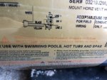
Nothing goes on the "Yellow" "2" lead, since the aquaplus is acting as the switch, correct?Aquaplus diagram.jpgMotor Diagram.jpgMotor LG.jpg

Does that seem right?
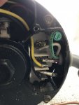
I got confused because they had a white lead on the line one pin and a black lead on what i perceived to be the 3 or 4 tab... See pic for incorrect, circuit tripping, connection...

Also, regarding the GFCI breaker, I assume since the common is going back to the relays there just isn't anything plugged into the middle pole on the breaker?

Thanks for the help!
 
There are 3 wires connected to the pump switch. Remove and discard (save in case you need them later) the black and yellow wires. Connect the white wire to terminal #3/4.

From automation, connect the common wire to terminal #1, the high speed wire to terminal #2 and the low speed wire to terminal #3/4.

For the GFCI breaker, the center terminal is for a neutral. Since you don't have a neutral, you leave the terminal blank.
 
Last edited:
well, I configured as discussed above, now the pump kicks on for a couple seconds, then shuts off. It's not tripping any breakers, sounds like a protection mechanism in the pump. If I leave it on it'll try again in a few seconds and turn off right away.

Odd thing is even if I set the "filter" to off on the aquaplus side the pump still kicks on, it's like the aquaplus isn't controlling it at all. I'm tempted to wire it back up to the switch and see if that does anything.

Are you certain about the config you recommended, I would think with Terminal 1 saying Line 1 and terminal 3/4 saying Line 2 those would have the power coming to them.

Looking at Terminal 2, it only had the yellow wire going to the switch, since the SWG is acting as the switch wouldn't that stay empty? Like this?
New Pump Wiring v2.jpg
 
The wiring at the pump is correct as I described. The problem is with the connection to the relays. Show that.

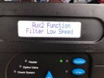
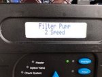
Did you go to configuration and set the pump type to two speed pump?
 
Can you show the actual wiring in the box and at the pump?

If you disconnect the wires from the pump and measure the voltage, you should get 240 volts between Common and High when High speed is selected and zero volts from Low to ground.

On Low speed, you should get 240 volts from Common to Low and nothing from High to ground.

On off, there should not be any voltage from ground to Common, High or Low.

Here's a different thread with the exact same issue. So, I know that it works like I described.


Your diagram looks correct.

If it's not working, the problem is with the wiring not being correct.
 
Last edited:
There are two sets of windings. Each winding has two ends.

To make the pump run on high speed or low speed, you power both ends of either winding.

The Common terminal #1 connects to one end of both windings.

The white wire connects to the other end of the low speed winding.

Terminal #2 connects to the other end of the high speed winding.

To activate the high speed, you power the common terminal and the #2 terminal.

To activate the low speed, you power the common terminal and the white wire. You can connect the white wire and the low speed wire directly or connect them both to terminal #3/4, which connects them together.

Your configuration looks good.

If it's not working, you probably made an error with the wiring.
 

Enjoying this content?

Support TFP with a donation.

Give Support
I opened the hood and everything looks correct, I'm worried when I initially hooked it up wrong I blew something... I'm outta time though, just finishing this build in mid October, In Wisconsin, so "Winter is Coming"... I'm going to hook it back up to the switch and see if it powers up. i really only need ti to circulate water for a couple days while I chem up the pool... I'll let you know if it works on the standard switch.
 
Thread Status
Hello , This thread has been inactive for over 60 days. New postings here are unlikely to be seen or responded to by other members. For better visibility, consider Starting A New Thread.