Hoping this is an easy one, I think i have it figured out, but would like confirmation.
I'm hooking up a Hayward Super Pump 2 speed to the Hayward Aquaplus SWG. I've tried several configurations, by accident mostly.
On the aquaplus side I have a 220v dual pole gfci breaker, and 2 relays - it's wired just like the diagram - 4 wires going to the pump. (Well, not counting the bonding wire).
Red - Low Speed
Black - High Speed
White - Common
Green - Ground
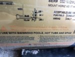
But on the pump side the diagram is a little more confusing since it's relating to the manual switch on the back of the pump. So i'm thinking I need to connect:
Red to Line 2 (low Speed)
Black to Line 1 (High Speed)
White to the white wire that was connected to the switch, for "common"
Green to the ground screw.
Nothing goes on the "Yellow" "2" lead, since the aquaplus is acting as the switch, correct?


Does that seem right?
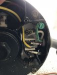
I got confused because they had a white lead on the line one pin and a black lead on what i perceived to be the 3 or 4 tab... See pic for incorrect, circuit tripping, connection...
Also, regarding the GFCI breaker, I assume since the common is going back to the relays there just isn't anything plugged into the middle pole on the breaker?
Thanks for the help!
I'm hooking up a Hayward Super Pump 2 speed to the Hayward Aquaplus SWG. I've tried several configurations, by accident mostly.
On the aquaplus side I have a 220v dual pole gfci breaker, and 2 relays - it's wired just like the diagram - 4 wires going to the pump. (Well, not counting the bonding wire).
Red - Low Speed
Black - High Speed
White - Common
Green - Ground
But on the pump side the diagram is a little more confusing since it's relating to the manual switch on the back of the pump. So i'm thinking I need to connect:
Red to Line 2 (low Speed)
Black to Line 1 (High Speed)
White to the white wire that was connected to the switch, for "common"
Green to the ground screw.
Nothing goes on the "Yellow" "2" lead, since the aquaplus is acting as the switch, correct?


Does that seem right?
I got confused because they had a white lead on the line one pin and a black lead on what i perceived to be the 3 or 4 tab... See pic for incorrect, circuit tripping, connection...
Also, regarding the GFCI breaker, I assume since the common is going back to the relays there just isn't anything plugged into the middle pole on the breaker?
Thanks for the help!


