Hayward pump starts, but is noisy and trips breaker.

The Bocephus

Bronze Supporter
Apr 8, 2020
25
Broussard, LA
Pool Size
52000
Surface
Plaster
Chlorine
Salt Water Generator
SWG Type
Hayward Aqua Rite Pro (T-15)
My Hayward pump (Hayward SP32202EE TriStar 2 HP Pool Pump, Dual-Speed, Energy Star Certified) is relatively new (Apr 9, 2019).
I replaced the starting capacitor about 6 months ago and everything worked great. Now, the pump will start, but will soon trip the breaker. I have removed the impeller and diffuser and there is/was nothing clogging it. The shaft feels like it spins freely, without any sort of binding or resistance. I even started the pump without the impeller installed and it made the same BAD sound and tripped the breaker.
I should add that after noting the pump was not on today, I cleaned out a lot of debris from my skimmers and pump strainer basket. I guess there is a chance that the strainers were so clogged that limited water supply to the pump caused motor damage? Seems unlikely. Maybe the start capacitor is not functioning correctly? Not exactly sure what my next troubleshooting steps should be.
 
I just replaced the Capacitor with a new one and I get the same problem. It starts, runs for 5-10 seconds and trips the breaker.
I should add, this is just the motor as it is not hooked up to the pump. Not sure if the no load condition could also cause the breaker to trip.
 
Last edited:
I am attempting to start in High. I just tried again and it is not tripping the breakers, tries to run a little longer, but stops. As I was removing the cap to test the insertion voltage to the motor, I noted that the motor housing is very hot. I cannot keep my hand on the case for more than a second or so. The thermal protection must be triggering.
I did check the voltage at the controller box going out to the pump and it was 240ish VAC.
Do I need to disconnect the motor and check voltage? I don't want to apply power to the motor, since it is obviously making it overheat.
 

Enjoying this content?

Support TFP with a donation.

Give Support
It was a working system up until today. I replaced the capacitor back in September, but working fine since then.
I don't know how to measure the windings. I will look for a guide online and revert.
I am not sure what you mean by measuring voltage line-to-line. I measured the voltage coming off the breaker in the control box before they entered the relays for the motor. I will disconnect the motor and check the voltages at those leads and revert.
I don't know anything about a centrifugal switch. I will have to research that and revert.
Thanks for your assistance. Sorry for my lack of understanding.
 
I am out of light and time. I will have to work on the winding resistance measurements tomorrow. I did get the following voltage measurements (High Speed set in controller):
  • Voltage between L1 and L2 = 247 VAC
  • Voltage between L1 and A = 83 VAC
  • Voltage between L2 and A = 67 VAC
 
I am out of light and time. I will have to work on the winding resistance measurements tomorrow. I did get the following voltage measurements (High Speed set in controller):
  • Voltage between L1 and L2 = 247 VAC
  • Voltage between L1 and A = 83 VAC
  • Voltage between L2 and A = 67 VAC
I suspect that you have a stuck relay and both windings are getting power at the same time.

Try powering just the high speed or low speed windings with the extra wire disconnected and not touching anything.

Verify the voltage during the test.
 
  • Voltage between L1 and L2 = 247 VAC
  • Voltage between L1 and A = 83 VAC
  • Voltage between L2 and A = 67 VAC
Verify by the wiring diagram, but I think that L1 is Hi speed, L2 is common and A is Low speed.

Starting on High speed, you should have 240 between L1 and L2 and 0 volts between L2 and A and zero volts between L1 and A.

I suspect that if you remove the wire from terminal A, the pump will probably run correctly.

I suspect that the low speed relay is stuck on or somehow activated at the same time as the high speed relay.

If you power both sets of windings at the same time, one winding is trying to make the rotor turn at 3,450 rpm and the other winding is trying to make the rotor turn at 1,725 rpm, which results in the rotor not turning at all.
 
Last edited:
When I tried with just the HI speed wires connected (L1 & L2), it made the same noise. I shut down power before it shut down itself. It seems as though the motor is spinning, just very slowly.
I then tried with just the LO speed wires connected (A & L2) and got nothing. I am thinking now, I should have taken voltage measurements during low speed test. I am a little hesitant to attempt to measure the HI speed voltage, based on the sound and heat it generates before shutting down. I don't have a lot of experience with motors, so not sure if it will do any damage.

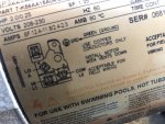
Motor_Label.jpeg
 
The motor might be damaged if both windings were powered at the same time.

Did you verify if both windings were being powered at the same time?

What controller do you have?

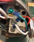
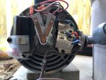
Do you have a picture that shows the entire wiring compartment including the centrifugal switch?

Remove the capacitor and the power wires and then test the resistance between L1 and L2, the resistance between L1 and A and the resistance between L2 and A.

Test for resistance between L1 and ground, L2 and ground and A and ground.
 
Last edited:
How do I check if both winders were powered at the same time?

The Controller is a rebranded Hayward, Blue Haven as Aqua Logic. I am pretty sure it is equivalent to a Hayward AquaPlus. They look just alike, but different stickers.

I took the following measurements.

Set to HI speed
L1 <-> L2 = 247VAC

Set to LO speed
A <-> L2 = 247VAC

Which capacitor (Dual Cap in compartment on top of motor or start cap inside the wiring compartment) do I remove for the resistance tests?
Wiring_Compartment.jpeg
 
The copper V is the contacts for the centrifugal switch.

They contacts need to be closed to start the motor.

It looks like there is a piece of grass holding the contacts open.

Remove the debris and try to start the motor.

Which capacitor did you replace, the one in back or the one on top?
 

Enjoying this content?

Support TFP with a donation.

Give Support
Thread Status
Hello , This thread has been inactive for over 60 days. New postings here are unlikely to be seen or responded to by other members. For better visibility, consider Starting A New Thread.