The purpose of this thread is to help out anyone in the future, so that they may not struggle with my struggles. Let my trials and tribulations be your education.
I have a Hayward H250 millivolt heater. All of this info should apply to all H series heaters, including H150, H200, H250, H300, H350, and H400. As always fix your equipment at your own risk, and if you're in over your head, call a professional.
I moved into my current house in late 2009, so 2010 was my first swim season. Our kids were young, and we couldn't justify heating the pool because we wouldn't get the use out of it. However, I recognized that the heater that was installed was a nice one, so I wanted to maintain it. Every year for (almost) the past 15 years, I've been chasing one problem or another to keep this thing functioning. It's not a statement of Hayward quality by any means. Our swim season is only 4 months long, we don't use the heater regularly, and it becomes a really attractive home for critters during the winter, so "troubles with operation" shouldn't be surprising. That said, I finally got the heater working the way it should for the first time in 13 years, and I'm sure the heater is almost 20 years old, so not too shabby. Here's a bit of knowledge, searchable on the interwebs, so that hopefully someone else can benefit from the tinkering I've done.
First, a couple of universal observations.
1. The millivolt thermopile assembly is kind of a poor design that invites problems. I've had to replace the whole thing once. Even so, it attracts dirt/debris/bugs. If the pilot won't light, one solution is to remove the nut and the machine screw, pull the whole thing out, and see if the piezo will create a spark. If it does, remove the compression nuts (one at the gas valve, one at the thermopile) and use compressed air to clean everything out. Even the smallest blockage will completely mess up the gas flow, and inhibit lighting the pilot light.
2. This thermopile generates a small voltage. That voltage travels across a circuit, and if the circuit is complete, the heater will fire. If the heater doesn't fire, there's a really good troubleshooting guide in the manual. HOWEVER, the decision tree assumes that only one switch in the circuit is defective. If only one switch is failed, the guide works beautifully. If more than one is failed, you hit a dead end, and the end result is "call someone". I think a better way is to check continuity across each individual switch. This will make it perfectly clear if/when more than one switch is failed, and which ones need to be fixed or replaced.
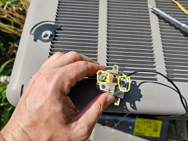
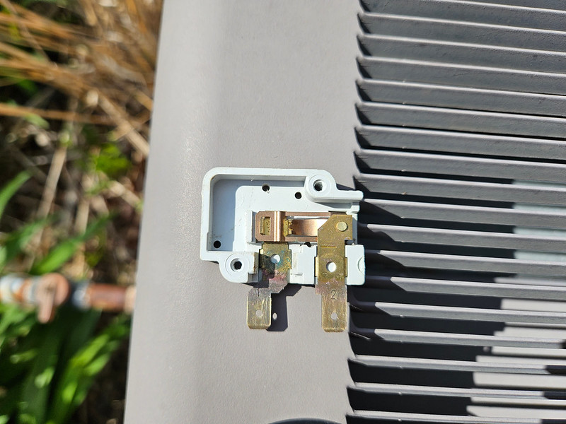
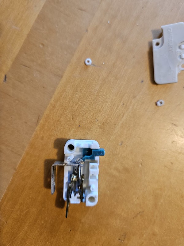
3. Another option is to start with the troubleshooting guide, but instead of jumping switch to switch, methodically add one switch and connecting wire at a time to determine where the breaks in the circuit are. I used this method to clean up the contacts on one of the limit switches (more in the posts below).
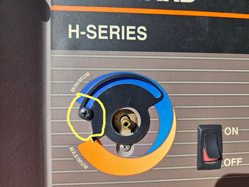
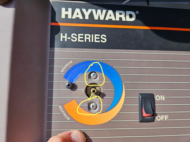
Over the years I've replaced the pressure switch, the system switch, and the thermopile/pilot assembly. About a year an a half ago, I determined the thermostat was bad, but at the time decided to kick the can down the road. This year, as part of the opening process, I tackled the entire system and decided to get it working. Here's what I learned....
I have a Hayward H250 millivolt heater. All of this info should apply to all H series heaters, including H150, H200, H250, H300, H350, and H400. As always fix your equipment at your own risk, and if you're in over your head, call a professional.
I moved into my current house in late 2009, so 2010 was my first swim season. Our kids were young, and we couldn't justify heating the pool because we wouldn't get the use out of it. However, I recognized that the heater that was installed was a nice one, so I wanted to maintain it. Every year for (almost) the past 15 years, I've been chasing one problem or another to keep this thing functioning. It's not a statement of Hayward quality by any means. Our swim season is only 4 months long, we don't use the heater regularly, and it becomes a really attractive home for critters during the winter, so "troubles with operation" shouldn't be surprising. That said, I finally got the heater working the way it should for the first time in 13 years, and I'm sure the heater is almost 20 years old, so not too shabby. Here's a bit of knowledge, searchable on the interwebs, so that hopefully someone else can benefit from the tinkering I've done.
First, a couple of universal observations.
1. The millivolt thermopile assembly is kind of a poor design that invites problems. I've had to replace the whole thing once. Even so, it attracts dirt/debris/bugs. If the pilot won't light, one solution is to remove the nut and the machine screw, pull the whole thing out, and see if the piezo will create a spark. If it does, remove the compression nuts (one at the gas valve, one at the thermopile) and use compressed air to clean everything out. Even the smallest blockage will completely mess up the gas flow, and inhibit lighting the pilot light.
2. This thermopile generates a small voltage. That voltage travels across a circuit, and if the circuit is complete, the heater will fire. If the heater doesn't fire, there's a really good troubleshooting guide in the manual. HOWEVER, the decision tree assumes that only one switch in the circuit is defective. If only one switch is failed, the guide works beautifully. If more than one is failed, you hit a dead end, and the end result is "call someone". I think a better way is to check continuity across each individual switch. This will make it perfectly clear if/when more than one switch is failed, and which ones need to be fixed or replaced.
3. Another option is to start with the troubleshooting guide, but instead of jumping switch to switch, methodically add one switch and connecting wire at a time to determine where the breaks in the circuit are. I used this method to clean up the contacts on one of the limit switches (more in the posts below).
Over the years I've replaced the pressure switch, the system switch, and the thermopile/pilot assembly. About a year an a half ago, I determined the thermostat was bad, but at the time decided to kick the can down the road. This year, as part of the opening process, I tackled the entire system and decided to get it working. Here's what I learned....
Last edited: