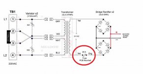
How did the Yellow and Orange wires get on the wrong terminals?
It is highly unlikely that it came like that from the factory.
The input voltage does not match the jumper configuration.
The jumpers are set for 230 volts and the input is 115 volts, so that won't work.
What breaker goes to the SWG?
It is highly unlikely that it came like that from the factory.
The input voltage does not match the jumper configuration.
The jumpers are set for 230 volts and the input is 115 volts, so that won't work.
What breaker goes to the SWG?