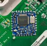
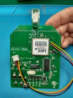
Has anybody figured out how to repair Pentair 520949 Antenna Board?

patterrr

0
Bronze Supporter
Jun 25, 2016
30
Denver, CO
Pool Size
15000
Surface
Plaster
Chlorine
Salt Water Generator
SWG Type
Pentair Intellichlor IC-20
Hello TFPs! My Pentair EasyTouch8 wireless controller is stuck on "NO COMMS" and I can't relink it. I believe the antenna board, Pentair 520949 (AKA 520946) has failed, which seems very common when searching online. The POWER LED is on solid red, and the 485 LINK / RF LINK LEDs flash red 6 times followed by a single flash of 485 LINK.

Given the ridiculous price to replace these (I'm an EE who designs production hardware and can say the production cost of these would be $10 - $30 each) and high failure rate, I'm wondering if anybody has figured out how to repair these? I can dig into it, but before spending a bunch of time reverse engineering and debugging, I'm hoping that somebody has already done that and can share what the failing component is.

Thank you!

PS: I'm hoping to eventually score a decent deal (<$350) for a ScreenLogic2 520500 adapter on EBay as a longer term solution, but the remote is handy for kids and guests.
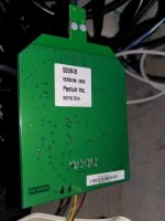
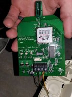
20230913_214337.jpg 20230913_214347.jpg
 
Hey Pat... I've got a pile of those cards that do the dreaded 6-flash (these are cards with good comm chips (U1), but still don't work). I haven't done much more with them yet besides solder on some test leads... maybe we can put our heads together.

If you grab the datasheet for the laird radio module you'll see that it uses serial commands... so I've soldered some test leads to a good card and dead card, with the intention of seeing if I can send or receive commands to/from it, or see any differences with a logic analyzer.

A bigger problem with these cards is that the laird module is not readily available, and neither is the firmware for the pic micro-controller (i've tried to read it off a working card but it's secured)... so if we determine that a laird module is dead, the only source I've found is to pull a module from something else (i.e. an easytouch2 or mobiletouch2 handheld controller with some other failure). But if the micro-controller is dead or somehow scrambled (which i think is less likely), we're out of luck unless there's a donor card with a good one.

Tom
 
Last edited:
Thanks for the message Tom.

My EasyTouch controller / subpanel is located in our basement as it's an indoor pool. The antenna board is also located indoors, and is in a spot that's inaccessible to contact. Therefore, I think I can rule out ESD and most likely lightening as we don't have any underground wiring or anything outdoors other than the main electrical service to the house, and no other equipment in the house has been damaged. Also, as you pointed out it appears that the microcontroller appears to be fine; it's obviously executing code to flash the LEDs. Our power has been going out pretty frequently lately.

I wish we could get info from Pentair about what type of failure causes it to give that blinking pattern to put us on the right track. But given the simplicity of the PCBA and the types of components on it, I think a hardware failure is unlikely. Perhaps an easy test though would be if you could measure the voltages on the two LDOs (U3 and U5) on one of your good boards versus one of the bad ones. But I'm venturing to guess that a firmware issue is the root of the problem if there is indeed no hardware issue.

Like you said the Laird module isn't available. Shockingly it was a $40 part which is strange that they'd choose it given the significant lower cost transceivers available. Anyways, it has an onboard configuration EEPROM, so just changing the part with a new one (assuming a person could get a new one) probably still wouldn't work without the EEPROM configured. Unless the MCU configures it at power-up. But I'm guessing if it did that, then it probably wouldn't be broken; instead, I think they configure it one time as part of their end of line test. My guess is that the MCU occasionally writes something to the AC4790 EEPROM, and our power went out during that write, causing it to become mis-configured. It then can't talk to the AC4790 due to the misconfiguration so stops working and blinks the error pattern. Sniffing the serial data with a Saleae or similar would definitely shed some light on what's going on. The solution might be as simple as reading the EEPROM configuration from the AC4790 on a good board and writing it to the AC4790 on the bricked board.

It's very tempting to drop the $400 on a new card just so that I can do this debugging... Although I really should prioritize a few other projects first :) Also, the one I have is a 520949 version 2030, but most around are version 2040. Do I need to replace with the same version to work with my remote, or would a 2040 work with my remote? I do see one version 2040 on EBay for less than $250...

Ryan
 
Hey Ryan,
I agree with everything you've said! I was thinking that the pic was there to set some initial configuration and then of course manage the flow of data between the radio module and the rs485 chip. I'll see if I can capture anything.

I'm almost positive I've checked the output of those regulators and found them to be good, and I likely checked the current draw of a good vs bad board as well... but I'll do it again tomorrow. (I usually check the power supply first when debugging anything)

As for the 2030 vs 2040 version, I think you'll be fine with the 2040. I've used boards with 2020, 2030 and 2040 and they've all worked - but the ones before 2030 take longer to sync for some reason (I wrote it up in another thread, but I can't find it now!).
 
Hi Tom,

The 520949 version 2040 for $215 on Ebay sold quick, unfortunately it was gone by the time I saw your reply. :( The rest are above $450 so I'll have to wait for another deal to come along to snag one for comparison debugging.

Maybe you've already found this, but it appears that Laird has a software utility for communicating with the radio: Laird Configuration and Test Utility Software - RAMP Modules

It would probably be a decent task to figure out the serial protocol enough to read and write the EEPROM. But perhaps the PIC could be held in reset to tri-state its UART, and then a USB-UART adapter connected to the lines so that this software can be used to read the EEPROM, then the same setup on a bad board to write the EEPROM. Probably easier said than done, but perhaps easier than a more manual process.
 
hah, yeah I've got that Laird utility on my laptop but haven't tried it yet. I was stuck on how to hook up my pic-kit (in uart mode) so I could talk to the Laird chip without blowing up the PIC... I was going to cut some traces because it didn't occur to me to just hold it in reset!
 
Interesting... I don't know why it took me so long to try the Laird tool, but I got it to work. I connected one of the 2020 firmware cards (that I cannot pair to anything) to a uart, powered up the card, and was able to read the radio!

The radio baud rate was set to 38400 (kept trying different ones until I found that 38400 worked), and then, because I entered AT command mode on the "Command" tab, I had to disable the "Read/Write with AT commands" option on the "PC Settings" tab before reading the radio on the "Configure" tab.

I've attached the output... you can actually copy the text, paste it into a text file and load it from the Laird tool. It'll show you all the settings in the GUI or EEPROM view.

I had pulled up Vcc and the 3 pins connecting the PIC to the radio probably a year ago and forgot I'd done it, so I didn't need to hold the micro in reset. I'll try a 6-flash card and a good card tomorrow.
 
Last edited:
0 1 2 3 4 5 6 7 8 9 A B C D E F
0000 41 45 52 4F 43 4F 4D 4D 20 49 4E 43 2E 0D 43 6F AEROCOMM INC.ÿCo
0010 70 79 72 69 67 68 74 20 32 30 30 36 0D 56 20 33 pyright 2006ÿV 3
0020 2E 34 2D 31 0D 41 90 FF FF FF FF FF FF FF FF FF .4-1ÿAÿÿÿÿÿÿÿÿÿ
0030 00 D6 0E 00 00 E3 FF 0A F4 05 E3 03 FF FF 02 FF ÿÖÿÿÿãÿÿôÿãÿÿÿÿÿ
0040 00 02 FA 00 02 A8 00 10 B8 FF FF FF 04 01 FF 40 ÿÿúÿÿ¨ÿÿ¸ÿÿÿÿÿÿ@
0050 01 03 FF FF FF FF 41 FF 02 FF FF 80 C0 B0 23 08 ÿÿÿÿÿÿAÿÿÿÿ?À°#ÿ
0060 00 20 00 0C A0 00 56 87 09 23 6C F3 FF FF FF FF ÿ ÿÿ ÿV?ÿ#lóÿÿÿÿ
0070 FF FF FF FF FF FF 01 FF FF FF FF E3 12 FF 32 FF ÿÿÿÿÿÿÿÿÿÿÿãÿÿ2ÿ
0080 FF FF FF FF FF FF FF FF FF FF FF FF FF FF FF FF ÿÿÿÿÿÿÿÿÿÿÿÿÿÿÿÿ
0090 FF FF FF FF FF FF FF FF FF FF FF FF FF FF FF FF ÿÿÿÿÿÿÿÿÿÿÿÿÿÿÿÿ
00A0 FF FF FF FF FF FF FF FF FF FF FF FF FF FF FF FF ÿÿÿÿÿÿÿÿÿÿÿÿÿÿÿÿ
00B0 FF FF FF FF FF FF FF FF FF FF FF FF FF FF FF FF ÿÿÿÿÿÿÿÿÿÿÿÿÿÿÿÿ
00C0 FF 90 FF FF FF FF FF FF FF FF FF FF FF FF FF FF ÿÿÿÿÿÿÿÿÿÿÿÿÿÿÿ
00D0 FF FF FF FF FF FF FF FF FF FF FF FF FF FF FF FF ÿÿÿÿÿÿÿÿÿÿÿÿÿÿÿÿ
00E0 FF FF FF FF FF FF FF FF FF FF FF FF FF FF FF FF ÿÿÿÿÿÿÿÿÿÿÿÿÿÿÿÿ
00F0 FF FF FF FF FF FF FF FF FF FF FF FF FF FF FF FF ÿÿÿÿÿÿÿÿÿÿÿÿÿÿÿÿ
 
I tried a 6-flash card and it can't read the radio...

So I think I've got two options:
1. take apart the module (it's based on the ti cc1010) and see if there's an eeprom chip - maybe the chip has worn out from too many read/write cycles? (I've repaired two tvs and a monitor that have had that problem)
2. pull the whole module and swap it with a donor (I've got an Easytouch2a wireless controller that I pulled the micro from to swap into a V1 board)
 
Last edited:

Enjoying this content?

Support TFP with a donation.

Give Support
Quick update... I haven't been able to read the eeprom of ANY of the "6-flash" boards I've got, but I was able to read the eeprom from a donor module (I cut open a bad easytouch2a remote). The remote module's eeprom was significantly different from the transceiver card but that might be ok.

I also pulled the top off of the working donor module... here's a pic of the innards, showing the cc1010 chip:
module_uncovered.jpg

This is how I wire up the cards so I can read the eeproms with a cheap cp2102 usb uart. I only connect gnd, rx and tx to the uart, and then power it with 12vdc on the comm port's red/black pins. EDIT: I also pull up the 2 pins for vcc (13,28), and the rx, tx and cts pins (24,25,26) going to the module... holding in reset did not work:
IMG_20231005_205018176_HDR.jpg
 
Last edited:
Nice work Tom, you made some really good progress! Thank you for documenting exactly what you did. It looks to me like there is no EEPROM in the Laird module, unless I'm missing it? That means they must be using the flash memory within the CC1010 to emulate an EEPROM. Typically flash memory allows far more write cycles than EEPROM, but on this old CC1010 it only allows 20,000 cycles. If they are writing to it on a regular period, then it's definitely possible to hit that 20,000 cycle limit in a handful of years. So that would be a good explanation for why you failed to access the EEPROM on the 6-flash card. That's pretty much the worst case scenario, if the flash on the CC1010 is literally worn out. Not much we can do about that :(

As a side note, I notice there isn't much RF circuitry on that Laird module, not even an LNA. I'm very impressed that the CC1010 has nearly the entire RF front end built into it.

Do you have any thoughts on anything else to try? It sounds like you tried quite a few 6-flash boards, how many in all? I'm impressed with your commitment to solving this. If you can't access the EEPROM on the Laird module I think we're pretty dead in the water. (n)
 
Hey thanks Pat... I hadn't looked up the specs on the cc1010 eeprom, but 20k is worse than I expected. Feels like the 1990's!

I tried reading the eeprom on 7 cards and a remote... 4 dead cards did the 6-flash-repeat and had 2030 firmware, 2 dead cards didn't do the 6-flash-repeat but had 2020 fw, 1 was a good/working card with 2030 dw, and the last was a working module from the easytouch remote. I could only read eeproms on the last 2.

I also only seem to get the 6-flash-repeat on 2030 fw... Interestingly - and kindof as expected - when I powered up a working 2030fw card, it flashed 6 times but did not repeat. Then I pulled up the rx, tx and cts pins and got the 6-flash-repeat... So the 6-flash-repeat pattern seems to indicate that the PIC can't read the module. I read the eeprom, soldered the pins back down, and it operated normally again. I haven't tried it on my working 2040 card, and don't have any dead 2040 cards to play with ☹️

I still want to take the shield off of a dead card, just in case there's another explanation. I've also got a cc10xx debugger/programmer here somewhere, so I may try that as well... Then of course I want to do a module swap with one of the bad 2030 cards I've got.

But yeah, if the cc1010 eeprom is dead I think the only chance of repair is finding a replacement or donor module... there's little chance the laird/aerocomm firmware is going to be available. I found a possible source in China for the ac4790-1x1 modules, but it seems dodgy... I may give it a go just for kicks.
 
Based on your tests, it sounds like the issue, with high confidence, is the MCU being unable to talk to the AC4790. If you're ambitious, you could use your debugger / programmer to see if you can read out the firmware from a good AC4790; chances are the memory is locked from JTAG reading, but if not then you could save that binary and program it to a new CC1010 replaced on an AC4790. Definitely would be easier to replace the AC4790 module, but like you said they are hard to find, and sketchy... Doing either would most likely bring the 520949 back to life.

I was able to score a halfway decent deal on a ScreenLogic 2 adapter module on Ebay earlier this week. I received it yesterday and installed it, and I gotta say that it made me very quickly lose interest in reviving my remote! Even though the app has a terrible rating on the Google Play Store, it is orders of magnitude better than the remote control. I still wouldn't mind bringing mine back to life for when somebody without the app wants to control the pool, but not sure the juice is worth the squeeze, especially since I don't have a CC1010 ICE or any experience with that MCU.
 
Ugh, connecting the ti tool to the chip is going to be a total pain in the a--. Like you said, the juice isn't worth the squeeze.

Best bet may be too sell that handheld on fleabay as long as the menu button works! I'm going to swap in a good module to see if it works, then I'm calling it.
 
Slightly interesting update... I pulled the "presumed bad" radio module off of a 2030fw 6-flash-repeat card and replaced it with a module whose eeprom I am able to read, and the device works! sortof.

I can't use it to pair an ET8 outdoor board running 2.190 with a handheld remote running 2.140... but if I first pair with another card, then this card can control the system and update the remote just fine. I may have my firmware versions too mixed up... so a remote running 2.160 and up might pair ok with this card. Need to look at my notes about firmware compatibility across uoc/uwc/cards.
 
Nice work! Sounds like you've determined that it's a failed Laird module for sure then, presumably the EEPROM. Too bad these modules are so hard to get a hold of!

I looked at selling my remote on ebay (it's in perfect shape), but there appears to be a lot of supply there right now so will keep my eye on it...
 
Thread Status
Hello , This thread has been inactive for over 60 days. New postings here are unlikely to be seen or responded to by other members. For better visibility, consider Starting A New Thread.