Goldline Controls AQR - Power, Generating, Chlorinate LEDs go on and off every minute

quiglda

Member
Aug 24, 2021
8
Columbus, GA
Hey Guys,

So I noticed the chlorine levels where not in sync with SWG after testing several times. Did all the obvious things like turning on Super Chlorinate, etc. I replaced T-Cell since it was under warranty. But then I noticed the lights going off and on. Any ideas besides replacing circuit boards?

Thanks in advance
 
For AquaRite, move the switch from auto to off and check all of the readings.

Move the switch back to auto and recheck the readings.

Move the switch to off for a minute and then back to auto and recheck the readings.

Switching the unit off and then back on makes the unit reverse polarity.

Report all readings.

What are the first seven characters of the cell and box serial numbers?

What is the actual salinity and how are you measuring it?

What is the T-cell size?

Is the T-cell size set correctly in settings?

To get the performance percentage of the cell in each polarity, divide the instant salinity reading in each polarity by the actual salinity reading.

For example, if the instant reading is 3,300 ppm and the actual salinity reading is 3,300 ppm, then the salt cell is working at 100%.

However, if the actual salinity was 3,800 ppm, then the performance percentage is 86.8%.

Anything over 75% is acceptable.

At75%, or lower, in either polarity, it's time to consider replacing the cell.

The instant salinity in both polarities should be about the same (+/- about 200 ppm).

You need to be really sure about the actual salinity reading.

You need to use a K-1766 salt test kit or a calibrated meter.

K-1766 Taylor Salt Test

Note that ProLogic, AquaLogic and AquaPlus use the Hayward T Cell.

However, the procedure to get the diagnostic readings is different.

Here is the procedure for ProLogic, AquaLogic and AquaPlus:

Go to the diagnostic screen, note the readings and then press the + button to reverse the polarity.

When the new numbers appear, see what they are.

Then, press + again and note the new readings.
 
Wow! Great approach and steps to diagnose. It confirms I am a amateur. I will work on getting that information. The short answer on the Chlorine reading is that our local pool store has a large lab that they test your water for free.
 
The short answer on the Chlorine reading is that our local pool store has a large lab that they test your water for free.

Not much credence is given to pool store testing around here. While you would think that a "professional" would be the best, unfortunately in most cases it is quite the opposite. Between employees who blindly trust the word of chemical sales representatives and high school kids working in the pool store for the summer you end up with poor results from their testing. Plus, the results of their "testing" is used to convince you that you need to buy things. Why do you think that testing is free?


But, what can you do?? We base our pool care system on accurate testing and only adding what the pool needs, when it needs it. To do that you need your own accurate test kit. Order a TF-100 Test Kit ™
 
Yes. I am very sceptical on there advice but they have never really tried to sell us anything and have helped us out by fixing Polaris for free etc. But I agree we should have our own testing kit.

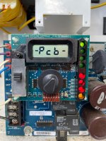
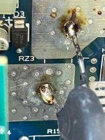
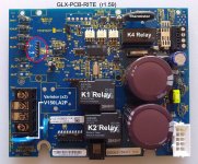
The problem I am dealing with now is I read the the document from JamesW and saw some pieces of solder on components under the Thermistor. So I would test the Thermistor. So I took out my handy fluke multimeter and followed the directions on what leads to apply (R15 and farthest pin from red lead) and a spark occured. Now I have the following on the display - PCB - and a lot of red lights (see Pic). I may have fried the board. Ugggh!
 

Attachments

  • IMG_2276.jpg
    IMG_2276.jpg
    438.2 KB · Views: 8
  • IMG_2277.jpg
    IMG_2277.jpg
    357.6 KB · Views: 7
For AquaRite, move the switch from auto to off and check all of the readings.

Move the switch back to auto and recheck the readings.

Move the switch to off for a minute and then back to auto and recheck the readings.

Switching the unit off and then back on makes the unit reverse polarity.

Report all readings.

What are the first seven characters of the cell and box serial numbers?

What is the actual salinity and how are you measuring it?

What is the T-cell size?

Is the T-cell size set correctly in settings?
You should have started with the requested readings.
 
The problem I am dealing with now is I read the the document from JamesW and saw some pieces of solder on components under the Thermistor. So I would test the Thermistor. So I took out my handy fluke multimeter and followed the directions on what leads to apply (R15 and farthest pin from red lead) and a spark occured. Now I have the following on the display - PCB - and a lot of red lights (see Pic). I may have fried the board. Ugggh!
Sorry, this happens! But you don't need a multimeter to run the diagnostics! The R15 is Negative and connected directly via trace to the BLK terminal on the top right-hand corner of the pcb. The adjacent Red terminal and both leads of the Thermistor are Positive (30 Volts DC when not chlorinating). I would assume that your Fluke multimeter is auto-ranging and so, it does not matter where you place the red and blk test leads.
But if the Fluke selector switch is incorrect, (ie, A or mA or Ω) it will definitely create a spark or a short circuit. I wonder why the 20A fuse did not blow! Or perhaps the spark is caused by the thermistor loose solder joint. Can you best describe where the spark came from? Did you just put welding marks on your test leads? Try to cycle the AC power to the PCB and see how it goes.
 
You should have started with the requested readings.
Agree. I did not follow your steps.
You should have started with the requested readings.
James, you are absolutely right and definately did not follow proper trouble shooting steps and got into trouble. I tried to run those and the screen is frozen and cannot cycle through them however I did run through the Diags before my screwup. Here is the data in bold. Other info in pics.

  • Default salt display - 4200
  • Pool temp - 87
  • Cell Voltage - When not generating, the voltage is about 30 to 32 volts dc. When generating, the voltage drops about 1 volt per amp of current. - This is all over the place anywhere from 2-19 as it keeps going off and on
  • Cell current - 0
  • Desired output (% of the knob) - 67 - 100P when generating its 67P when off 100P
  • Instant salinity - 0 Negative Zero
  • Product name - AL - 0
  • Software revision (r.XX) - 1.55
  • Cell type T-9
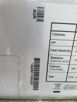
Model AQR, SN * #A0907-1034226
AquaRite Model SN.jpg

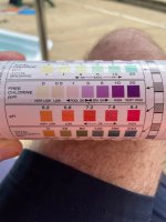
Test Results
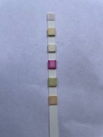
Test Guide.jpgTest Strip.jpg
 

Enjoying this content?

Support TFP with a donation.

Give Support
It was probably just a bad thermistor.

The thermistor was already replaced once.

Most likely, the board is now fried and you need a new

Sorry, this happens! But you don't need a multimeter to run the diagnostics! The R15 is Negative and connected directly via trace to the BLK terminal on the top right-hand corner of the pcb. The adjacent Red terminal and both leads of the Thermistor are Positive (30 Volts DC when not chlorinating). I would assume that your Fluke multimeter is auto-ranging and so, it does not matter where you place the red and blk test leads.
But if the Fluke selector switch is incorrect, (ie, A or mA or Ω) it will definitely create a spark or a short circuit. I wonder why the 20A fuse did not blow! Or perhaps the spark is caused by the thermistor loose solder joint. Can you best describe where the spark came from? Did you just put welding marks on your test leads? Try to cycle the AC power to the PCB and see how it goes.

Thanks for the details. I think the Spark came from Thermistor lead. I had the right setting to DC. I did recycle but still has the - PCB - reading on LCD. I am going to replace the Thermistor first. If that doesnt work I guess I will replace PCB. My gut tells me I fried the board. As I said to JamesW - I should have followed his guidance. Up side is I am learning alot.
 
Thanks for the details. I think the Spark came from Thermistor lead. I had the right setting to DC. I did recycle but still has the - PCB - reading on LCD. I am going to replace the Thermistor first. If that doesnt work I guess I will replace PCB. My gut tells me I fried the board. As I said to JamesW - I should have followed his guidance. Up side is I am learning alot.
Going by your initial post, "But then I noticed the lights going off and on", this is probably caused by a loose Thermistor lead solder point. With the AC power off, measure the resistance of the thermistor. It should read 2Ω. If ok, try to resolder the leads. Don't skimp, be generous on the solder! With the salt cell disconnected, set the DVM to measure DC voltage. Place the Blk test lead to R15 post and the Red to the thermistor lead farthest from the red terminal. Turn on the AC power, the DVM should read at least 31Vdc and the power LED should turn on solid. If "pcb" still shows on the display, the first thing I would do is to re-flash the sw. I have a copy of r1.55 sw to share if interested. Or upgrade to sw r1.59. Or perhaps take the easy way out, replace the pcb.
 
Going by your initial post, "But then I noticed the lights going off and on", this is probably caused by a loose Thermistor lead solder point. With the AC power off, measure the resistance of the thermistor. It should read 2Ω. If ok, try to resolder the leads. Don't skimp, be generous on the solder! With the salt cell disconnected, set the DVM to measure DC voltage. Place the Blk test lead to R15 post and the Red to the thermistor lead farthest from the red terminal. Turn on the AC power, the DVM should read at least 31Vdc and the power LED should turn on solid. If "pcb" still shows on the display, the first thing I would do is to re-flash the sw. I have a copy of r1.55 sw to share if interested. Or upgrade to sw r1.59. Or perhaps take the easy way out, replace the pcb.
Really appreciate the feedback. Not ready to do the easy way yet :). Is there any documentation I could read on re flashing the firmware that you could refer me to. I have old school flash card not sure if I have all the correct interfaces. Would also need sw. Can you share electronically. Not sure if I should upgrade to 1.59.
 
Reloading the sw is a risky business and not a guaranteed fix. But what you got to lose if the mainboard is brain dead. You may want to swap out the pcb to confirm.
I can email you a copy of the sw r1.55, just pm me. I use PICKit 3 Programmer and MPLAB (free edition). You'll find the step by step instructions here. It is the same for the Aquarite except, Under Device you choose "PIC16F73" and the PICKit connects to J9 (see pic below). It is very important to observe the Pinout, improper connection might brick your pcb.

Hayward_GLX-PCB-RITE_J9.jpg
 
Thread Status
Hello , This thread has been inactive for over 60 days. New postings here are unlikely to be seen or responded to by other members. For better visibility, consider Starting A New Thread.