Flow switch sensitivity

I installed a Hayward Salt system about a year ago. I had a lot of problems at the time with the flow switch. It would not allow the generator to stay on long. I realized that if I had the valve positioned so that it would go through the gas heater I would have the problem. If I changed the valve so it would bypass the heater, the system would work. I now have the system connected to solar heat. The generator will not work at all since I have to have it going through the heater and I am sure it is the flow switch. I'm not sure how sensitive they are nor the quantity of water that must flow through the switch to keep it in the positon to turn on the generator. It may be that I just need to purchase a larger pump. The current pump is a Hayward 1.5 HP super pump.

I could run the pump to heat the pool and then bypass the heater to generate chlorine but that will be a pain to do often and will require running the pump more.

What to do?
 
Welcome to TFP!

The Hayward SWG's are some of the lowest required flow to operate them, they only need around 11GPM. That pump should more than enough to handle the flow requirements.

Please tell us more about the plumbing. What size of pipes, any water directed elsewhere before the flow switch, etc.

Does the flow switch have 12 inches of straight pipe before the switch and is it installed with the arrows pointing with the flow of water?
 
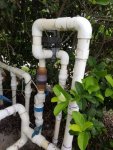
20170820_184737.jpg
Here is the photo. I did make sure I had the 12 inches during installation. I had to raise the stack to make sure it met this requirement. That is why it is higher than the other stacks. The manual valve in front of the switch is used to bypass the heater and solar. The arrow is pointing down. I tried to move it a little off straight down I the hopes that would fix the problem, but it didn't. The water will goes from the pump through the filter, and then to the one way valve, chlorine cell, flow switch then to the pool If close the valve in the picture the water will go to the solar if the solar is calling for heat, then to the gas heater then back to the one way valve...If the SPA is on it bypasses all of this. The Spa valve is almost at the top of the stack.
 
I'm not seeing enough in this picture to see the flow that you are talking about with the heater and solar bypass. I'll let some plumbing experts chime in, but I think the ball valves are killing the flow. I can count five ball valves, one check valve and an automated valve. I would think the automated valve is for the solar and if that is on, the cell would not get any water through it which would shut off the SWG. If this is the case, that design is dangerous as the flow switch should not be the device to turn off the SWG.
 
Rob,

I don't think I would be going out on a limb to say that I suspect the layout of your plumbing is the most likely cause for your flow issues...

I wish I could follow the flow, but without being able to see all the inputs and outputs I don't really have a clue...

In general, you want all the flow from your pump to pass through the cell... and the cell should be the last thing before the water is being returned to the pool... After any solar or heater... So, if you had two pool returns and a waterfall, the cell would be before them and any valves that control the returns or waterfall would be after the cell..

Also I have no clue as to why there is a check valve right before the cell... What is the purpose to this check valve?

Thanks,

Jim R.

The check valve is for the spa. It prevents the spa from draining to the level of the pool. It is fairly new since I replaced it when I installed the salt system. The spa was draining and I thought it would be a good idea to replace it. When I opened the old valve I found a piece of something in it that was preventing it from closing. Should I remove it and just allow the spa to drain? It may be adding too much resistance. However, the chlorine generator does work when I bypass the gas heater. The gas heater is fairly old. I am not sure how it is made. I assume that it is made of stainless steel on the inside but maybe not and it is corroded adding resistance. It is a Sta-Rite heater.
 

Enjoying this content?

Support TFP with a donation.

Give Support
I think I figured out the problem. I have the cell installed going to the spa instead of the pool. I will change the plumbing tomorrow. Hope it works better. What caused me to think this way was the pipe going to the spa is a 3 inch and going to the pool it is 2 inch. I thought the larger pipe was going to the pool and spa but now when I turn off the valve marked "return" the water stops going to the pool so I am assuming that is the pipe going to the pool.
 
Rob,

I don't think I would be going out on a limb to say that I suspect the layout of your plumbing is the most likely cause for your flow issues...

I wish I could follow the flow, but without being able to see all the inputs and outputs I don't really have a clue...

In general, you want all the flow from your pump to pass through the cell... and the cell should be the last thing before the water is being returned to the pool... After any solar or heater... So, if you had two pool returns and a waterfall, the cell would be before them and any valves that control the returns or waterfall would be after the cell..

Also I have no clue as to why there is a check valve right before the cell... What is the purpose to this check valve?

Thanks,

Jim R.

Yessir there are some plumbing issues there
 
I thought I was done. I re-plumbed the salt cell and flow switch but had a leak. I had to purchase a new flow switch fitting because I didn't have enough pipe to do it with what was installed. I glued everything together and then tried to screw the flow switch in. It does not fit! The threads are the right size but it seems that the hole tapers to the point that it will not let the switch through. I was thinking about buying a bit and drilling it out so the switch will fit through the hole. I though that I should ask if anyone else has had this problem and their solution.
 
Thread Status
Hello , This thread has been inactive for over 60 days. New postings here are unlikely to be seen or responded to by other members. For better visibility, consider Starting A New Thread.