Finally installed home made automation to include variable position valve control.

Rich D

0
Bronze Supporter
Aug 3, 2018
1,086
MA
Just thought I would share this in case anyone is looking for home made variable valve positioning.

My prior valve control was just 2 wall switches to control waterfall -> IFCS and skimmer -> mian drain Valves. That can be seen here.

I have now installed 2 ewelink 4ch controllers with 6 relays that now let me control both of these - 3 way Valves and set them to any position. I can now use the wall switches or my phone to fully control the valve actuators.

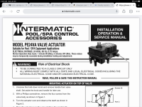
The variable valve positioning is done by simply applying power to the actuator for a specific amount of time then removing the power once the valve is in the correct position. For example to set the valve to 50% I would apply power to the valve for 45 seconds to get into a fully opened position then apply power in the other direction for 20 seconds and then remove the power. This leaves the valve opened 50%.

This can be achieved bu using these..


Wich will allow you to use the inching function to activate the valve for a exact time frame. However this would mean using a relay for each required valve position as well as having to push a button to get to the fully opened position then wait the 45 seconds and push another button to open the valve to the required position.

I use a android automation app called 'Tasker' wich allows me full control over the ewelink devices. So I can set up my own routines in Tasker that will do all the automatic timing for me so I would not need to use the inching setting. This app will allow me to push 1 button on my phone and then have the relays put power to the valves for whatever timing I need for as many times as I needed.
 
A $22 switch and a couple of free apps that can do what the big three can't.

Pretty cool!
Yup.. When we had the pool built I forget what the up charge was for the automation however I remember it being significant. So I figured at some point if I really wanted it I would be able to do some sort of home innovation. I have several partial valve positions I use often, so I would have felt cheated if I payed the big bucks for automation that can't even do variable position control. I would imagine there "Automation" controllers are still built with vacuum tubes and neon displays?? :ROFLMAO::ROFLMAO:
 
  • Haha
Reactions: Rancho Cost-a-Lotta
I did my own automation using similar relays. I had no automation so I also added pump speed control and SWG on/off control. I use Alexa for the routines. I've fine tuned a few things along the way, but the system works flawlessly (link in my sig). Next year I'll work on heater control with a Sonoff TH-16 switch. I've kicked around the idea of partial-movement valve control for my spa spillover and slide/waterfall, but it's not "really" necessary and I didn't feel like messing around with the programming of new routines. If I need a project, I may give it shot someday.

So it sounds like you used a separate relay channel for each direction of valve travel...is that correct?

Good job on the system!
 
So it sounds like you used a separate relay channel for each direction of valve travel...is that correct?
Correct. I used the interlock feature of 4 channel relay so there is no need to turn off the power to one leg of the actuator before applying power to the other because the interlock will only allow one of the four channels to be 'on' at a time.
 
  • Like
Reactions: Rancho Cost-a-Lotta
Hey Rich…nice! My setup also allows me to postion valves to any location and I use it in my scheduling and testing. It uses the same basic mechanism as yours (timing and relays) and I have found that the movement of the actuators is VERY linear and predictable based on the time that current is applied. Mine can be positioned 0-100% in 1% increments. It might seem like overkill but a 1% change makes a substantial difference in some cases, mostly at the higher rpm/psi ranges needed for IFCS operation. I only have two valves in my system but one is important because I use it to throttle/bypass my IFCS vs wall returns flow. I wish I had a valve to control between skimmers/main drain (as you do) but my system is older and wasn’t designed with that option.

My 3-way valves (both return side) are installed differently than most because they use one of the end ports as the input to divert water flow between the other two outlets (center/other end) Thus the full range for my 3-way valves is only a 90 degree movement to choose between 100% flow one way or the other. I imagine your 3-way valves are setup to use a 180 degree range (the main input/output is probably the center port of the 3-way?).

It seems our actuators must be somewhat different as mine rotate the 90 degrees in a little less than 11 seconds…so for a 180 degree turn would require, at most, 22 seconds. Does your 45 second ‘reset’ just have margin built in or is that a real difference in our actuators’ timing? I think mine are Intermatic actuators.
 
Does your 45 second ‘reset’ just have margin built in

Very cool..

Yes it does. My 50% position is at 10 seconds so they seem to be very close. They are the Jandy actuators with 180 degree turn.


It sounds like we do similar things with the IFCS. My 3 way valve is for IFCS and Waterfall. I have found if run the rpm's at 2950 and just crack the valve to give minimal flow to IFCS (5 seconds) this will give full suction on the main drain and minimal flow out of the IFCS so it sweeps the floor into the main drain instead just blowing debris everywhere. I do this for a few hrs every night wich allows us to see the waterfall around dinner time and does a low flow floor clean. Then I do a normal 2950 rpm clean with full flow to IFCS for 2 hrs after we go to bed.

I will also pause my IFCS on a zone that gives the best whirlpool affect and run full skimmer during the day at 1500 rpm. This does a great job of keeping the surface spotless during the day. To fine tune the zone I leave on for skimming I check the direction the heads are pointing
and then have the app cycle the IFCS on and off until the heads are pointing ion the best direction to get a perfect whirlpool affect. So I just enter the number of cycles I need into the app and it sets the head position for me..
My heads have 12 positions, so it's basically just like reading a clock to tell how many times to cycle the cleaning system.
 
Last edited:
Rather than use a timer have you tried to integrate a hall sensor? I believe that is how the Jandy SmartJVA board works. It goes through a calibration and after it is done, it has a high degree of accuracy on where the JVA is located.
 

Enjoying this content?

Support TFP with a donation.

Give Support
My setup also allows me to postion valves to any location and I use it in my scheduling and testing.
Wow.. I just read through "some" of your automation post. Very impressive. I wish I had seen that before attempting to build mine. I was very concerned about powering both legs of the actuator at the same time so I went to great lengths to avoid that. I saw in your thread it really should not be a issue. I also had a lot of trouble figuring out how to give control to the manually operated wall switches and the automation side so they could both work independently of each other. This was finally solved with a timer relay controlling a latching relay.
 
  • Like
Reactions: jonpcar
Wow.. I just read through "some" of your automation post.
Rich…I haven’t updated that thread in quite awhile but plan on doing so at some point. I’ve made quite a bit of progress beyond that thread. I’ve been working towards a goal and have taken a lot of little steps but so much more to do and so little time, haha.

I don’t know if you followed the valve feedback discussion (extra switches in the actuators) in that automation thread…they let me know when my actuators have hit a rail and so a “recalibration” can take place every time that happens. They also provide a means to “check” that the valve actuators are working as expected.

You might be interested in some of the experiments I am eventually planning for my IFCS…in fact my IFCS was the inspiration for starting my pool automation project given the limitations of my previous Hayward Ecommand4. When I get around to completing those, I will post an update. It’s probably still out a year or so given my current time commitments, haha.
 
I don’t know if you followed the valve feedback discussion (extra switches in the actuators) in that automation thread…they let me know when my actuators have hit a rail and so a “recalibration” can take place every time that happens. They also provide a means to “check” that the valve actuators are working as expected.
I did just go back and read the entire thread (kinda skimmed the chlorine and acid pumps as I do not anticipate installing those in the near future, However I am close to retirement so I suppose it could happen... :) ) For now I find just running the actuator to the end and timing a return position will suite my needs. The next script I will write for the Tasker app will allow me to simply input a desired percentage of the valve position to be set.

I was very intrigued by this post of yours..

"Question...do you know if these type motors will endure a lot of movement? They seem to get warm quickly. What I had in mind is a change (partially back and forth) about every 30 seconds to implement a very fast In-Floor-Cleaning-System “sweep” of my pool. I could completely sweep the pool in less than 30 minutes rather than the current ~1hr...maybe just a pipe dream, because I wouldn’t want to burn an actuator motor over it."

Have you acquired any experience with a somewhat continuous operation of these motors? As noted above I am already doing something similar by setting my one zone to the best position for skimming. This can take up to 22 180 degree rotations.

Thanks, Rich..
 
You might be interested in some of the experiments I am eventually planning for my
Looking forward to it.. :)..

Does the AA system allow you to pause the distribution head on a single zone? I believe that will be my next automation venture. The Paramount head has a small switch on top that will pause the flow at the current zone. So I currently have to wait for that zone to be active then go over to the head and manually switch it to pause it. Then I check the heads position and now can use the app to rotate them to the correct position for the whirlpool affect for skimming operation. It sounds like someone had the forethought to install side returns in addition to your IFCS. Knowing what I know now I would have definitely paid to put in conventional side returns at the time of the build. My pool only has 2 returns. One is the IFCS and the other is the water fall.

So I will need to monitor that zone for being active (not sure on the best approach for that) then I will need a servo control on top of my distribution head to rotate the switch 90 degrees. I do not believe I ever be able to detect the position of the heads so there will always be a small munual step of checking head position then having the app rotate the heads.
 
Have you acquired any experience with a somewhat continuous operation of these motors?

Only in experiments and for relatively short periods of time. Attached are the specifications for my intermatic actuators (see duty cycle)…what I am planning will probably exceed these specs. Similar to what you are doing, I am going to cycle my IFCS/walll return valve ONCE during the zone UP time causing the popups to rotate and effectively sweep TWO positions per zone selection (rather than ONE postion per zone selection). This will almost halve the pool sweep time from about an hour to 35 minutes. But the plan is to do this for my IFCS clean time of approximately 2 hours (currently I run my IFCS about 3 hours a day), so that is where exceeding the specs may come into play.


Does the AA system allow you to pause the distribution head on a single zone?
….
So I will need to monitor that zone for being active (not sure on the best approach for that) then I will need a servo control on top of my distribution head to rotate the switch 90 degrees. I do not believe I ever be able to detect the position of the heads so there will always be a small munual step of checking head position then having the app rotate the heads.

Yes, I can stop it using the manual lever as well…and have toyed with the idea of a servo to stop the zone rotation to implement my “fast sweeping” as described in the previous paragraph. In that case I would step through all 12 positions while each zone is stopped. Currently I don’t believe that approach would be significantly better than the doubling approach I have decided upon because I would still need “stop/dead/wait time” between position changes. I estimate the end result would still be about 35 minutes per complete pool sweep.

As far as determining which zone is active…I determine that with a PSI transducer on my IFCS head. Each zone has a unique pressure and in my case one is significantly different than the others (psi and timing)…so I can keep track of the zone with that. As far as determining popup head position…I have also speculated about that too and NOTHING comes to mind, sorry…haha.

You might want to check out the first post of this thread where I post the graph of the PSI profile of my IFCS (the 4th or 5th graph in that post)…it might give you some ideas.


Attachments

  • 64BAD350-73A9-471B-A673-0BA5B307C653.png
    64BAD350-73A9-471B-A673-0BA5B307C653.png
    608.3 KB · Views: 12
Attached are the specifications for my intermatic actuators (see duty cycle)
Thanks for the data sheet.. My Jandy sheet does not mention 'duty cycle' however I would assume it would be very similar to yours. It would appear I am already way over the recommended duty cycle when I set my head positions.


As far as determining which zone is active…I determine that with a PSI transducer on my IFCS head. Each zone has a unique pressure and in my case one is significantly different than the others (psi and timing)…so I can keep track of the zone with that. As far as determining popup head position…I have also speculated about that too and NOTHING comes to mind, sorry…haha.
Wow.. Thank you for that, That was one option I had not thought of. Using that information I believe I should be able to "track" the head position by monitoring each activation of the zone. IE - if head is at 12 o'clock then after 12 activations it will be at 12 o'clock. I realize there are a few variables that will get this out of sync, However it seems a better approach then cycling the zone valve 22 times.... :). Besides the exact position of the heads is not "critical" for a swirl affect. Any head position in that particular zone will push the surface debris toward the skimmer so if I notice it is out of sync at any point I can simply resynchronize it. I can usually tell even from the kitchen window if it is in the correct position just by seeing the turbulence against the walls when at high rpm. I have my pump set to go to high rpm several times during the all day skimming just to free up some junk in any corners. This is where the servo for the pause would also help. I could then just simply un-pause the distribution head aa few times a day to move stuff out of the corners instead of a high rpm blast.

Could you post some information on the sensor you use for this and how you are able read the data from the sensor.

We are on vacation this week so I have found some down time to read through your IFCS optimization thread. Very informative... However I did not see one approach tested on there that I have been using that seems to work well for me. I call it a low flow floor sweep. I will put the minimal flow through the heads (just enough to pop them up) and maximize the suction in the floor drain by running at high RPM. This is easy in my case because of my 3 way valve for IFCS and water fall. I realize your options are limited in that department. This tends to do a much better job of sweeping heavy debris into the drain instead of blowing it over the drain.

Thanks, Rich..
 
Last edited:
If you want a technical read, check out the below which is a good primer on hall effect sensors to determine motor position.

 
  • Like
Reactions: jonpcar
Could you post some information on the sensor you use for this and how you are able read the data from the sensor.

Rich…I think the approaches we have taken towards automation are very different. My background is microcontrollers and so the approach I have taken is to design the pool controller (hardware/software) as a module that operates independently and directly controls the valves/pool pump/lights/Stenner pumps/etc. It reacts to stimulus (sensor inputs, time, queries, commands) with responses (relay changes, status reports, pump commands, etc).

In my case, the pool controller is constantly reading/monitoring the psi values within the system and can make decisions based on the values read. I currently don’t do much with these values except report them and/or generate an out-of-spec warning . In a couple cases the pool controller will shut down the system if a catastrophic failure has been detected (no prime, no pressure when there should be). But I have plans for additional functions based on the psi values if and when I ever get to them…like the fast IFCS sweeping I have described.

The psi transducers are described in my “pool controller” thread but those sensors require an AD converter and software to be useful. I am not sure how your “Tasker” based system would use them…I think you would need some hardware at your pool pad (raspberry psi, arduino, etc) to interact (control/read/interpret) with the psi sensors to accomplish anything useful. But I am old school in regards to my ignorance of the additional options that have become available over the last 10 years…so there might be a way…


However I did not see one approach tested on there that I have been using that seems to work well for me. I call it a low flow floor sweep. I will put the minimal flow through the heads (just enough to pop them up) and maximize the suction in the floor drain by running at high RPM.

Rich…my experiences have made me skeptical that any IFCSs direct debris “towards” a drain. I feel it is totally random whether or not debris approaches the main drain and gets sucked in…a deep end main drain would have increased chances.

But, like you, I have found that drawing all suction from the main drain (during IFCS operation) AND increasing that main drain suction (by increasing the GPM drawn through it) DOES capture more of that debris that happens by the main drain…it becomes more like a vacuum cleaner. If you have 2”+ plumbing, I imagine your “low flow floor sweep” is sucking 90+ gpm through that main drain at 2950 rpm…mine would be. I suspect you could also get good results by “cracking open” the waterfall (to increase gpm) but still send the most significant portion of your gpm through the popups…but you would know your system best and have probably tried that.

Using the low flow method would be problematic for me for a couple reasons. My popups require significant pressure/gpm to fully raise and then “rotate to the next position.” It requires about 20-25gpm through the popups to do this reliably. This could be the fact that my popups are 2nd generation 1991 technology and the springs are stiffer than newer popups (the springs pull the popups down when they are not activated, but these springs must be “overcome” when popping up).

Also, sending lower gpm through my popup head valve significantly impacts the zone rotation time. My A&A system uses a water paddle wheel to rotate between zones. Because each zone has 12 positions (like yours), at normal IFCS psi (40-50gpm in my system), it takes about 1 hour for my system to completely “sweep” the pool once. Lowering that to 20-25gpm more than doubles that and I would require longer clean times than my current 3 hours (about 3 complete sweeps) a day. Actually 3 hours is overkill for me but it is relatively cheap ($20 month for pump operation which includes 3 hours IFCS operation and 12 hours skim time/day). Eventually I will change my IFCS cleaning to a deeper clean but only do it every few days…especially during the off-season
 
The psi transducers are described in my “pool controller” thread but those sensors require an AD converter and software to be useful. I am not sure how your “Tasker” based system would use them…I think you would need some hardware at your pool pad (raspberry psi, arduino, etc)
That is what I figured but just wanted to be sure. Going that route might over complicate things too much and I have not yet used raspberry or arduino yet. The best for my approach would be a wireless sensor to get the data directly to a android device. Hopefully I can just use something like this to get a accurate read on the pressure.


This pressure monitor approach is by far the best option so I will get there one way or another... :)


This could be the fact that my popups are 2nd generation 1991 technology and the springs are stiffer than newer popups (the springs pull the popups down when they are not activated, but these springs must be “overcome” when popping up).
Ahh, yes. My heads are weighted and simply rely on gravity to pull them down, so it takes very little pressure to pop them up.
Also, sending lower gpm through my popup head valve significantly impacts the zone rotation time.
This is true for my system as well. For now I really just use this whenever I run the waterfall. We like to have it going around dinner time because we have a great view of it from the kitchen while prepping, grilling, eating, and clean up. So for those times it's a win win...

Thank you very much for taking the time to reply.. This is very helpful information.. :)
 

Enjoying this content?

Support TFP with a donation.

Give Support
Thread Status
Hello , This thread has been inactive for over 60 days. New postings here are unlikely to be seen or responded to by other members. For better visibility, consider Starting A New Thread.