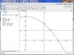
filter pressure vs flow rate

iam4iam

LifeTime Supporter
May 5, 2012
257
Johnson City, TN
1) I recently replaced my pump (just updated signature) and noticed that the clean filter pressure is only 10 PSI as opposed to 12 PSI with the old pump. Does this mean that the flow rate on the new pump is basically only 80% of the flow rate on the old pump? I'll take that trade off, since my old pump used about 1.5 kW,* and the new one says 0.71 kW. If my 80% flow rate assumption is correct, I'll need to run it 25% more time to get the same turnover, but if my 1.5 kW calculation was anywhere close, I'll still be using roughly 35% less electricity! :D

2) For a given pump, I assume that flow rate and filter pressure are inversely proportional, but I do not assume that the constant of proportionality is 1--i.e. I assume that GPM=k/PSI , but not that k=1. In other words, when my pressure increases from 10 PSI to 15 PSI (a factor of 3/2), I assume that my flow rate has decreased proportionally, but not necessarily be a factor of 2/3. Does the variation relationship depend on the pump and filter? Any idea of a typical variation equation for flow rate vs filter pressure?

*Power based on rough calculations using my power meter. That info wasn't legible on old pump, and neither was HP.
 
This one is a tricky question. A lot has to do with the size of plumbing, HP of pump, and head pressure, which all works together with the sand filter and how many main drains, skimmers and returns you have. I am not the foremost expert, but I can tell you that this is not simple math. Not necessarily will you have to will you need to run the pump 25% more to get the same turnover.

Mas985 is an expert in this field. Hopefully, he will chime in.
 
I,

It just does not matter... We have found that the requirement to have x water turnovers per day is just an old wife's tale and not all important.

I run my VS pump at 1,200 RPM and could care less what my magic turnover number should be. Apparently my pool does not care either... :p

At that speed my filter pressure is only 2 PSI...

Good deal on your electricity savings and thanks for posting,

Jim R.
 
I realize that neither of my original questions really matter, and that what does matter in the end is how clear the water is, which, thanks to TFP, is pretty darn clear--at least until the pool water had to remain stagnant for 5+ days when my filter broke. Both questions, especially #2, are really more just matters of curiosity. That said, since I know how much time I had to run my old pump to keep the water clear (only 4 hrs/day!!), it would be nice to have confirmation that 5 hrs/day with the new pump would be equivalent.

By the way, regarding #2, I am not interested in actually calculating the flow rate. Although I love math, the number of variables involved in that calculation, and the fact that I could not determine all of their values anyway, makes that calculation way beyond my level of curiosity. I am simply curious about the range of typical variation constants for the relationship between flow rate and filter pressure.
 
1) Flow rate is not likely 80% of what is was before ... it is not linear, like you are asking about in #2
2) It is not linear, and it would be a function of everything: pump, filter, equipment, plumbing layout, etc
 
Okay, it just occurred to me that it wouldn't matter what the value of k is in GPM=k/PSI (question 2). If the two variables do, indeed, vary inversely, then if you double one, the other is halved. Does one perhaps vary inversely to the square root of the other--GPM=k/sqrt(PSI)--or something like that?
1) Flow rate is not likely 80% of what is was before ... it is not linear, like you are asking about in #2
My 80% assumption was assuming that GPM=k("clean" PSI), all other things being constant. Perhaps GPM=k(sqrt("clean" PSI)), or something of the sort? Is that what you mean by it not being linear?
2) It is not linear, and it would be a function of everything: pump, filter, equipment, plumbing layout, etc
I know there are many other variables involved, but they are all constants in my specific application, and would therefore all make up part of the "k" I am asking about. Kind of like PV=nRT in chemistry, but you are only interested in the relationship between P and V, with n and T remaining constant.
 
If you knew the discharge pressure of your pump you could figure out flow by using the pump curve for the pump.

I am a mechanical engineer and want to know as much as i can about my pumping system. I installed a gauge by the discharge of my pump and a flowmeter. The gauge allowes me to see the pressure drop across my filter real easy.

I got a flowvis flowmeter off ebay at a good price.
 
The pump affinity law describes how pressure, flow and power are related.

If the impeller diameter or speed is doubled, flow is doubled, pressure is 4x (2^2) and power is 8x (2^3).

For example if you have a pump that has a flow rate of 100 gpm, 16 psi and 1600 watts and you reduced the impeller speed or diameter to half, the flow would be half, the pressure would be 4 psi and the power would be 200 watts (theoretical, real world power would be about 1/6).

If you had a set number of gallons you wanted to move, you would run twice as long but use 1/6 the power so the energy used would be 1/3.

Based on the affinity law, the flow will be about 91% of original and power draw will be about 76% of original.

Also, to estimate flow from a pump curve, you need to add the pressure side head loss and the suction side head loss to get total head loss in feet of head.

So, you would need to put a vacuum gauge on the suction side.
 
If you knew the discharge pressure of your pump you could figure out flow by using the pump curve for the pump.
I'm not interested in finding the actual flow, although that would be interesting.

I installed a gauge by the discharge of my pump and a flowmeter. The gauge allows me to see the pressure drop across my filter real easy.
So the pressure reading on the filter gauge isn't the output pressure of the pump?

If the impeller diameter or speed is doubled, flow is doubled, pressure is 4x (2^2) and power is 8x (2^3).
So if I am understanding you correctly, you are basically saying that the new pump has different impeller speed and/or diameter, which accounts for the pressure being 80% of old pump? If I am understanding your description of the affinity law, since my pressure with the new pump is 80% of my old one, my flow would be sqrt(80%) of original, which is about 89%. That is close to the 91% that you propose--did I miss something?
 
I'm not interested in finding the actual flow, although that would be interesting.

So the pressure reading on the filter gauge isn't the output pressure of the pump?

So if I am understanding you correctly, you are basically saying that the new pump has different impeller speed and/or diameter, which accounts for the pressure being 80% of old pump? If I am understanding your description of the affinity law, since my pressure with the new pump is 80% of my old one, my flow would be sqrt(80%) of original, which is about 89%. That is close to the 91% that you propose--did I miss something?

The pressure on the discharge of the filter is lower than the discharge pressure of the pump. There is friction (pressure loss) thru the fittings and filter.
 

Enjoying this content?

Support TFP with a donation.

Give Support
So if I am understanding you correctly, you are basically saying that the new pump has different impeller speed and/or diameter, which accounts for the pressure being 80% of old pump? If I am understanding your description of the affinity law, since my pressure with the new pump is 80% of my old one, my flow would be sqrt(80%) of original, which is about 89%. That is close to the 91% that you propose--did I miss something?
Pumps are designed for a specific task. The task might be to provide high pressure and low flow, like a booster pump. The task might be to provide high flow at low pressure, like a waterfall pump. The task might be to provide medium flow at medium pressure. The impeller design is specific to the application. The diameter is just one of the parameters that can be varied. The thickness of the vanes can be varied as well.
When using the affinity law, typically the diameter or speed is used to simplify the equations.
ID = Impeller Diameter.
F = Flow.
H = Head Loss (Pressure).
P = Power.
ID1/ID2 = F1/F2
(H1/H2) = (F1/F2)2
10/12 = (F1/100)2
Sqrt(10/12)(100) = F1
F1= 91.287
(P1/P2) = (F1/F2)3
P1= (91.287/100)3 (100)
P1 = 76

10/12 = 0.8333
The square root of 0.8333 is 0.91287
Oh my gosh. I did understand! I was using 0.8 instead of 10/12!!! It's a good thing I'm not an engineer!! :oops:

So what about the relationship between pressure and flow for the same pump (my original question #2)? Clearly there is some sort of inverse relationship there.
 
https://www.hayward-pool.com/pdf/literature/maxflo-xl-medium-head-pump-series-LITMAXFLXL13.pdf

The above has a pump curve for your pump that shows the pump flow rate at any specific head. To get total head loss, you convert return pressure from psi to feet of head by multiplying by 2.31 and you add it to the suction head loss, which is the vacuum pressure (often measured in inches of mercury (In.Hg)) converted to feet of head. To convert from In.Hg to feet of head, multiply by 1.133
 
:paddle:
Oh my gosh. I did understand! I was using 0.8 instead of 10/12!!! It's a good thing I'm not an engineer!! :oops:

So what about the relationship between pressure and flow for the same pump (my original question #2)? Clearly there is some sort of inverse relationship there.

Ah ha! You did understand! 10/12 = 0.8333 and 0.8 is well within "engineering approximations" for any value of +/-10%! Because of the number of variables involved, the answer your original question #2 is: "It depends." Every pool is different due to the variables already mentioned. The best way to determine the answer to your question is to test your system and capture the data to determine the relationship between flow rate and filter pressure for your system. That data probably won't transfer to anyone else's pool but may provide the empirical answer to the question your asking.

:goodjob:
 
Because of the number of variables involved, the answer your original question #2 is: "It depends." Every pool is different due to the variables already mentioned. The best way to determine the answer to your question is to test your system and capture the data to determine the relationship between flow rate and filter pressure for your system. That data probably won't transfer to anyone else's pool but may provide the empirical answer to the question your asking.

It makes sense that it would be different for all pools, but wouldn't all pools have a similar GPM=k/PSI^n equation, where n is fixed for all pools and k would depend on all the other variables mentioned, but would be constant for any given pool, since all the variables mentioned are constant for any given pool? Clearly it is an inverse relationship, but basically I am asking whether it is a linear inverse relationship, or an inverse square relationship, etc.

In other words, if my pressure changes by a factor of 9/4, does my flow change by a factor of 4/9, or 2/3, or 16/81, or what?

The "power" of the inverse relationship would be the same for all pools, wouldn't it? Does that question make sense?
 
In other words, if my pressure changes by a factor of 9/4, does my flow change by a factor of 4/9, or 2/3, or 16/81, or what?
Again, it is related to the affinity equations. In general, any pool plumbing can be reduced to a very simple equation:

Head Loss (ft) = C * GPM^2

Where C is the plumbing constant. The filter pressure is a representation of the return side (post filter) head loss. If you have two known pressures, you can calculate the flow rate ratio. So if your pressure changes by a ratio of 9/4 than the square root of that is an approximation of the change in flow rate or 1.5:1. However, you should also take into account the filter height above the pump. In most cases, that is about 3' which causes a change in pressure of -1.3 PSI. So the change in flow rate ratio is actually sqrt((9+1.3)/(4+1.3)) = 1.4. Not much different from the approximation.

Both the pump's head curve and the plumbing's head curve are parabolic but are orthogonal to one another. So for a specific RPM, there is only one crossing point of the plumbing curve and the pump's head curve. This is called the operating point. When changing the RPM, the pump's head curve moves up and down but the plumbing curve remains the same. So the operation point also changes.


The "power" of the inverse relationship would be the same for all pools, wouldn't it? Does that question make sense?
One thing to be careful of is that the affinity equations relate to the pump, not the pump's motor. Power in the affinity equation is hydraulic power delivered to the water. It is not the same as the electrical power delivered to the motor although they are related by efficiency. Hydraulic power is proportional to head * flow rate which is why it is a cubed factor in the affinity equation. But yes, the hydraulic power could be fit to an equation such as:

Hydraulic Power = D * RPM^3

Where D is related to the pool plumbing as well but it is not the same for every pool. The plumbing plays a role in the relationship of head and RPM/Flow rate. For electrical power, you could use an equation such as this:

Electrical Power = F * RPM^3 + E

Where E is related to the efficiency of the pump/motor combination.

I use all these approximations in the "Pool Tools" spreadsheet (see signature) to estimate the operating points of pumps on plumbing.

For more information on all of this, you can read the Hydraulics 101 sticky in my signature.
 
Again, it is related to the affinity equations. In general, any pool plumbing can be reduced to a very simple equation:

Head Loss (ft) = C * GPM^2

Where C is the plumbing constant. The filter pressure is a representation of the return side (post filter) head loss. If you have two known pressures, you can calculate the flow rate ratio.
I understand that the filter pressure is a representation of return side head loss, but this equation only makes sense to me if you are comparing two pumps. The pump that can create more pressure will move more water through the plumbing system.

However, with a given pump, an increase in return side head loss (represented by filter pressure) means a decrease in flow rate! That is why we have to eventually backwash our filters!

What I am wondering about is the relationship between filter pressure (head loss on return side) and flow rate for one pump, i.e. all variables related to the pump are constant.

By the way, I was actually reading some of your Hydraulics 101 post ... very slowly ... prior to your reply! Maybe the answer I am looking for is in there, but I just haven't made it that far yet. :D
 
What I am wondering about is the relationship between filter pressure (head loss on return side) and flow rate for one pump, i.e. all variables related to the pump are constant.
That is basically related to the pump head curve. It too is a parabolic curve but orthogonal to the plumbing curve. You can usually fit a pump's head curve to the following formula:

Head (ft) = Hm * (1 - (Q/Qm)^2)

HM & Qm are the max head and flow rate axis intercepts. But to create a formula that is related to just the filter pressure is a bit more complicated because the head loss on the suction side of the pump also factors into the equation above and cannot be ignored. The pump's head curve is for the total head (suction + return) and is independent of the plumbing put on the pump. But if you try to formulate a head curve equation that separates return and suction pump head, you would then make the formula dependent on the plumbing it is attached to so it is no longer a general formula that can be used for all plumbing systems.

However, if you are only interested in the effects of your return side changing it's plumbing curve with the suction side plumbing curve remaining constant, then you could formulate something like this:

Return Head (ft) = Hm * (1 - (Q/Qm)^2) - Suction Head

Suction Head (ft) = Cs * Q^2

where Cs is the suction side plumbing curve constant but then you would need to figure out what Cs is. That is why I created the spreadsheets to make the whole process easier and more general.
 
Okay, I think I see the graphical perspective now after studying the pump curve vs system (plumbing) curve. So if I am right, added pressure due to filtered debris essentially creates a new plumbing system, moving the system head curve toward the head axis, which moves the operation point along the pump head curve in the same direction.

Unfortunately, I also see now how the relationship between pressure and flow cannot be simplified into a simple inverse relationship like I was thinking, but I can use the head curve for my pump to compare water flow at different filter pressures (approximately anyway, since I'm technically only taking into account return side head when looking at filter pressure). That way, if, say, I decide to backwash when water flow is 75% of what it is when the filter is clean, I just find the point on the pump head curve where flow is 75% of what it is when clean, which I determine by what the pressure is when the filter is clean.

I used PSI=head/2.31 to create a graph of my pump curve (PSI vs flow):

Capture.jpg

Clean filter pressure (after adding DE) is 10.5 PSI. Flow at this point is about 60 GPM. So if I want to backwash when flow decreases to 45 GPM, I wait until PSI reaches 17.

I am questioning the accuracy of my numbers and graph, since my pump manual says max recommended flow rate for 1.5" pipe is 45 GPM. Again, this may be because I am not figuring in suction head into the equation. Am I on the right track, at least in theory (if I had the correct pump curve)?

Speaking of which, what is the recommended % decrease in water flow for backwashing, or is it just personal preference? Is there a "filter efficiency" curve? I know that the filter filters more effectively as it becomes dirty, but decreased water flow counters that to some degree, and it is the amount of stuff being filtered per unit of time that matters, it would seem. Do you see where I am going here?
 
Okay, I think I see the graphical perspective now after studying the pump curve vs system (plumbing) curve. So if I am right, added pressure due to filtered debris essentially creates a new plumbing system, moving the system head curve toward the head axis, which moves the operation point along the pump head curve in the same direction.
This part is correct.


I used PSI=head/2.31 to create a graph of my pump curve (PSI vs flow):
Not exactly. Remember that the pump's head curve represents total head while the filters pressure represents only the head loss from the gauge to the pool. What you are doing is ignoring the rest of the plumbing head loss which will lead to incorrect results.


I am questioning the accuracy of my numbers and graph, since my pump manual says max recommended flow rate for 1.5" pipe is 45 GPM.
That is a recommendation, not an absolute limit. Flow rates can and do exceed those recommendations.


Speaking of which, what is the recommended % decrease in water flow for backwashing, or is it just personal preference?
The current TFP recommendation is for a 25% increase in filter pressure. In most cases, this results in less than a 15% decrease in flow rate. So there really is no reason to calculate the flow rate if you follow the pressure recommendation.


But again, if you are interested in estimating flow rates at various filter pressures, the spreadsheet in my signature takes into account all aspects of the plumbing and does everything you are trying to do but more accurately.
 

Enjoying this content?

Support TFP with a donation.

Give Support
Thread Status
Hello , This thread has been inactive for over 60 days. New postings here are unlikely to be seen or responded to by other members. For better visibility, consider Starting A New Thread.