
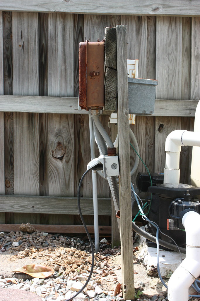
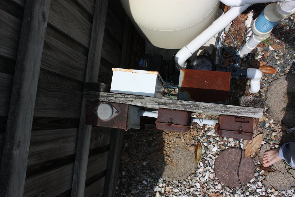
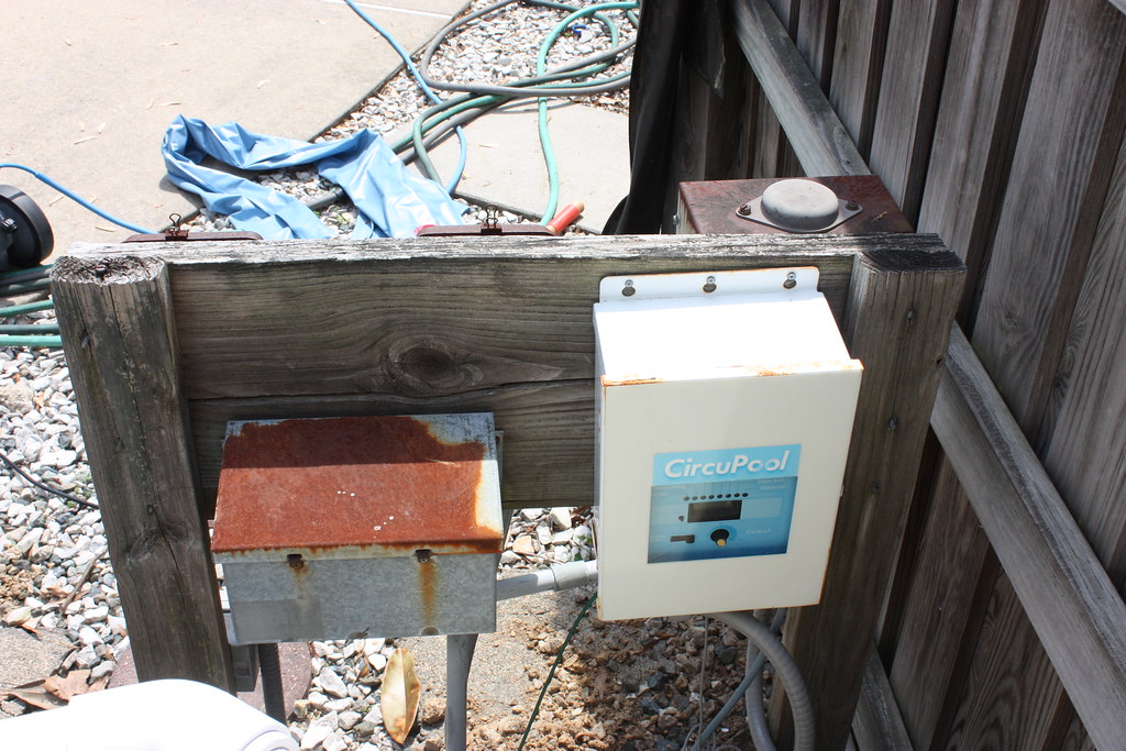
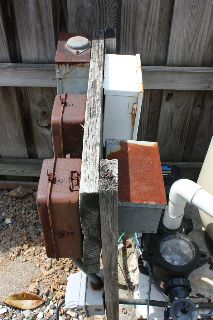
Currently, I have a sub panel, a pump timer, a filter timer, a light transformer, SWG control, and GFCI outlet. The timers are in bad shape. The enclosures are rusted, do not seal, and are held shut with paper clamps. Additionally, the flimsy plastic gaurds that protect the live terminals are compromised. With two kids, something needed to be done.
I found a Intermatic T4000RT3 on Amazon warehouse deals for $133 and couldn't pass it up. It contains 8 breaker locations, an integrated 300W transformer for the light, and one new timer mechanism. In the end, I could have everything I have now with only this new box and the SWG controls. MUCH neater. Now I just need to get the wires to go where needed.
My problem is modifying the current conduit locations to match the new box. I have two 1/2" solid PVC electrical conduits (one through the cement pump pad to the pool light, other beside (electrical feed from house) that need to be redirected. If there is too much movement, I'll need to extend the wires inside them also. I'm looking for recommendations and techniques to get this done "the right way".
Here are some pictures.


Lin for entire Pool Album, including above photos
The main feed is on the far end, closest to the fence and the light conduit is center'ish running through concrete. Additionally, the T4000RT3 has the transformer in its lower left, so the mains need to enter the box on the bottom center or bottom right side. I would like to keep the boxes facing outward for access to the controls. Because of the fence, there is not enough room to just plop the box on top of the mains conduit stub and face it outward. Additionally, the light conduit needs to be cheated over so it can enter the box.
Current "Best Idea":
Since the T4000RT3 is quite a bit taller, I need to extend the 2x4s up another 12" or so. To do this I would make a half lap scarf joint between existing wood and the extension, install the new 2x12 on each side of the joint, and possibly reinforce other side with a galvanized metal plate.
When I reattach a pair of 2x12"s horizontally, I would do so on the other side of the 2x4s (pumpside). This would allow me to place the T400RT3 on top of the light conduit and only modify the mains path. To do that, I would use a pair of conduit bodies so I can make the turns and install wirenuts inline to extend the wiring. I might get by with only one and an 90 radius elbow. The disadvantage is that the T4000rt3 has a side port for an outlet. The 2x4 post would block access, so I would need to continue to have an external outlet box.
Is this a good plan? Is there an easier way to do this?
I found a Intermatic T4000RT3 on Amazon warehouse deals for $133 and couldn't pass it up. It contains 8 breaker locations, an integrated 300W transformer for the light, and one new timer mechanism. In the end, I could have everything I have now with only this new box and the SWG controls. MUCH neater. Now I just need to get the wires to go where needed.
My problem is modifying the current conduit locations to match the new box. I have two 1/2" solid PVC electrical conduits (one through the cement pump pad to the pool light, other beside (electrical feed from house) that need to be redirected. If there is too much movement, I'll need to extend the wires inside them also. I'm looking for recommendations and techniques to get this done "the right way".
Here are some pictures.
Lin for entire Pool Album, including above photos
The main feed is on the far end, closest to the fence and the light conduit is center'ish running through concrete. Additionally, the T4000RT3 has the transformer in its lower left, so the mains need to enter the box on the bottom center or bottom right side. I would like to keep the boxes facing outward for access to the controls. Because of the fence, there is not enough room to just plop the box on top of the mains conduit stub and face it outward. Additionally, the light conduit needs to be cheated over so it can enter the box.
Current "Best Idea":
Since the T4000RT3 is quite a bit taller, I need to extend the 2x4s up another 12" or so. To do this I would make a half lap scarf joint between existing wood and the extension, install the new 2x12 on each side of the joint, and possibly reinforce other side with a galvanized metal plate.
When I reattach a pair of 2x12"s horizontally, I would do so on the other side of the 2x4s (pumpside). This would allow me to place the T400RT3 on top of the light conduit and only modify the mains path. To do that, I would use a pair of conduit bodies so I can make the turns and install wirenuts inline to extend the wiring. I might get by with only one and an 90 radius elbow. The disadvantage is that the T4000rt3 has a side port for an outlet. The 2x4 post would block access, so I would need to continue to have an external outlet box.
Is this a good plan? Is there an easier way to do this?