Ever since I read Jerryt's firmware update post back in 2015 I've wanted to swap the micro-controller chip on a "V1" Easytouch with one that will make a "V2" Easytouch... I finally did it tonight and it works! Figured I'd document the process in case anybody else felt like tinkering...
Background: the V1 and V2 boards are identical except for the microcontroller used. The V1 microcontroller only has 64k of flash which can only fit firmware up to 1.060, and the V2 boards have a 128k flash chip. I wrote a more detailed post about it here: What's the deal with Easytouch versions 1 and 2?
To do the swap, the first step was to get a microcontroller with 128k flash... I had an Easytouch V2 remote with a bad keypad, so I cut it open to grab a donor microcontroller. The indoor, outdoor and wireless controllers all use the same chip but I'll have to update the firmware since the wireless controller firmware is different than the outdoor.
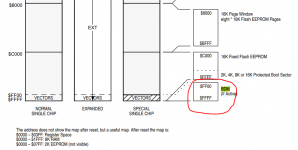
The main benefit to using a donor chip was that I didn't know if the bootloader was part of Pentair's firmware file, and the thing won't run without a bootloader! Another user (Xulan) in Jerry's thread swapped the chips on their Suntouch? but I never got a reply on whether they had to write the bootloader separately. My guess is they did not, and the bootloader is contained in the firmware file... because the firmware update routines appear write to ALL flash locations on the chip, I figure it must contain the bootloader code. I can verify this if I do another transplant with a new blank chip.
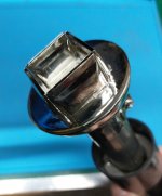
To pull the chip, I first added some lead solder (lower melting point than the lead free stuff) and lots of flux to all the pins. I then used my hot air gun with this QFP tip to remove the chip:
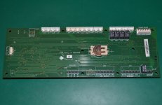
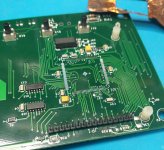
Here's my V1 board with the chip pulled off. just gotta go around with some solder wick and clean up the pads:
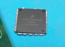
Here's the old chip... see the 9S12A64 marking (the "64" indicates the flash size). Pretend you don't see the capacitor that came off with the chip... I used a heat shield!
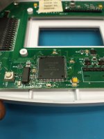
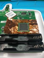
Getting ready to scavenge the donor chip. Not really sure why I used the heat shield again since this is now a donor board:
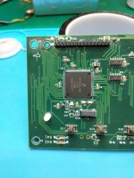
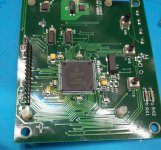
Donor chip fitted on the old V1 board (still have to clean up the flux a bit):
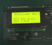
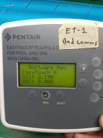
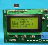
After re-fitting the LCD and updating the firmware to an Easytouch V2 Outdoor 2.190... it lives! Guess I gotta pull off that "V1" sticker now/
For my next transplant I'll use a fresh chip rather than a donor... I've got an Easytouch V1 indoor controller with a bad comm chip, so I figure I might as well convert this one to a V2 when I pull the LCD and replace the comms. If all goes well I can use it for testing on my bench.
Background: the V1 and V2 boards are identical except for the microcontroller used. The V1 microcontroller only has 64k of flash which can only fit firmware up to 1.060, and the V2 boards have a 128k flash chip. I wrote a more detailed post about it here: What's the deal with Easytouch versions 1 and 2?
To do the swap, the first step was to get a microcontroller with 128k flash... I had an Easytouch V2 remote with a bad keypad, so I cut it open to grab a donor microcontroller. The indoor, outdoor and wireless controllers all use the same chip but I'll have to update the firmware since the wireless controller firmware is different than the outdoor.
The main benefit to using a donor chip was that I didn't know if the bootloader was part of Pentair's firmware file, and the thing won't run without a bootloader! Another user (Xulan) in Jerry's thread swapped the chips on their Suntouch? but I never got a reply on whether they had to write the bootloader separately. My guess is they did not, and the bootloader is contained in the firmware file... because the firmware update routines appear write to ALL flash locations on the chip, I figure it must contain the bootloader code. I can verify this if I do another transplant with a new blank chip.
To pull the chip, I first added some lead solder (lower melting point than the lead free stuff) and lots of flux to all the pins. I then used my hot air gun with this QFP tip to remove the chip:

Here's my V1 board with the chip pulled off. just gotta go around with some solder wick and clean up the pads:

Here's the old chip... see the 9S12A64 marking (the "64" indicates the flash size). Pretend you don't see the capacitor that came off with the chip... I used a heat shield!

Getting ready to scavenge the donor chip. Not really sure why I used the heat shield again since this is now a donor board:

Donor chip fitted on the old V1 board (still have to clean up the flux a bit):

After re-fitting the LCD and updating the firmware to an Easytouch V2 Outdoor 2.190... it lives! Guess I gotta pull off that "V1" sticker now/

For my next transplant I'll use a fresh chip rather than a donor... I've got an Easytouch V1 indoor controller with a bad comm chip, so I figure I might as well convert this one to a V2 when I pull the LCD and replace the comms. If all goes well I can use it for testing on my bench.


