The SL32 legs are easy to bend and will work on either board. The AS32 legs are not easy to bend and only really work on the AS32 board. I would always get the SL32 thermistor to make replacement as easy as possible for either board.

Circuit Board Aquarite Goldline SWG
- Thread starter Henry M
- Start date
You are using an out of date browser. It may not display this or other websites correctly.
You should upgrade or use an alternative browser.
You should upgrade or use an alternative browser.
C0d3Sp4c3
Well-known member
- Dec 10, 2018
- 333
- Pool Size
- 20000
- Surface
- Plaster
- Chlorine
- Salt Water Generator
- SWG Type
- Hayward Aqua Rite (T-15)
I am not disagreeing with you! According to the OP he ordered the AS32. If the thermistor solder pads on his pcb have the provision to accept the AS32 series then there's no need to bend the legs. Done that many times and as observed, the AS32 is known to outlast the SL32. Anyway, I'm just trying to help if I may.
They are saying that the old thermistor was a SL32 model and that the AS32 does not fit.If the thermistor solder pads on his pcb have the provision to accept the AS32 series then there's no need to bend the legs.
In the below picture, someone drilled two new holes. They could have made it work by bending the legs of the SL32 thermistor to fit the wider AS32 holes. However, the AS32 thermistor legs are not easily bendable to fit the hole spacing of a board that originally came with an SL32 thermistor.Ordered model AS32 2RO25 new thermistor. Turns out the gauge of the contact "legs" are too flat, wide & spaced too far apart to fit onto my Main Circuit Board. The gauge of the contact legs on the old termistor are thin.
You can probably make the AS32 thermistor work by drilling new holes, but I would go with the SL32 thermistor instead of drilling new holes.
C0d3Sp4c3
Well-known member
- Dec 10, 2018
- 333
- Pool Size
- 20000
- Surface
- Plaster
- Chlorine
- Salt Water Generator
- SWG Type
- Hayward Aqua Rite (T-15)
Just for clarification, the through-holes on the pcb as shown in the above pic in red arrow is the exact fitment for the wider AS32 footprint. He would not need to bend the legs and no drilling. All he needs to do is to remove the old solder from the through-hole and solder the AS32 in place.
They do not have the board with the AS32 holes shown in the picture.the through-holes on the pcb as shown in the above pic in red arrow is the exact fitment for the wider AS32
The original board comes with just the holes spaced for the SL32 thermistor. It does not come with extra holes.
The new board with the AS32 thermistor comes with only the holes spaced for the AS32 thermistor.
In the picture, the board originally came with an AS32 thermistor. Someone drilled the extra holes to make a SL32 thermistor fit without bending the legs.
C0d3Sp4c3
Well-known member
- Dec 10, 2018
- 333
- Pool Size
- 20000
- Surface
- Plaster
- Chlorine
- Salt Water Generator
- SWG Type
- Hayward Aqua Rite (T-15)
For the Aquarite sw r1.55 and r1.58, the thermistor solder pads are predrilled at the pcb production line to take either SL32 or AS32 series. The through-holes are tinned but noticeable.
Do you have a picture of a board like that?For the Aquarite sw r1.55 and r1.58, the thermistor solder pads are predrilled at the pcb production line to take either SL32 or AS32 series. The through-holes are tinned but noticeable.
The poster can check to see if the holes are there and use them if they are.
Last edited:
C0d3Sp4c3
Well-known member
- Dec 10, 2018
- 333
- Pool Size
- 20000
- Surface
- Plaster
- Chlorine
- Salt Water Generator
- SWG Type
- Hayward Aqua Rite (T-15)
Unfortunately, I don't take pictures of every AQR pcb's that I have worked on in the past. But the r1.55 pic I posted above was brand new out of the box prior to me upgrading it to r1.59
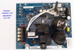
Here's another one from INYO website. It has AS32 on it but if you may notice, the red arrow is pointing to the SL32 through-hole. Please note, the thermistor is blocking the other side but they are visually noticeable for the skilled electronic techs.
Source> http://www.inyopools.com/Products/44401352080479.htm
Attachments
Ok, thanks for sharing the information. I did not know that some boards came like that.
They might have done that when transitioning from the old thermistor to the new thermistor to use up the stock.
The poster can verify their board and use the wider holes if they have them.
They might have done that when transitioning from the old thermistor to the new thermistor to use up the stock.
The poster can verify their board and use the wider holes if they have them.
What was the reason for upgrading from the r 1.55 to the 1.59?But the r1.55 pic I posted above was brand new out of the box prior to me upgrading it to r1.59
C0d3Sp4c3
Well-known member
- Dec 10, 2018
- 333
- Pool Size
- 20000
- Surface
- Plaster
- Chlorine
- Salt Water Generator
- SWG Type
- Hayward Aqua Rite (T-15)

The ProLogic circuit board can also provide power to the T-Cell.
Do you know why it does not need the thermistor?
Do you think that the thermistor is even necessary?
What would happen if it wasn't there?
Could you just use a piece of solid copper wire instead of the thermistor?
Do you know why it does not need the thermistor?
Do you think that the thermistor is even necessary?
What would happen if it wasn't there?
Could you just use a piece of solid copper wire instead of the thermistor?
C0d3Sp4c3
Well-known member
- Dec 10, 2018
- 333
- Pool Size
- 20000
- Surface
- Plaster
- Chlorine
- Salt Water Generator
- SWG Type
- Hayward Aqua Rite (T-15)
Sorry, my knowledge is limited to the Aquarite pcb's and I have not ventured out exploring other models.
You could probably use a jumper wire but I would not suggest it as a permanent solution. The link below has some valid pieces of information as to why the thermistor is integrated into the cicuitry.
Capacitor Inrush Current
As to the r1.59, the coil of the k4 relay energized at approx 500ms after the AC power is applied to the board. Well, that is according to my ageing O'scope.
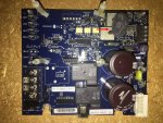
Need some expert advice, for this dilemma continues, and correcting it has some degree of urgency to it as it is going on 3 weeks with no SWG function. The issue is outlined in previous posts. I've learned from the help you all have provided that I've a r1.59 GLX-PCB-RITE main board. This saga began when I noticed it is getting electricity, but does not function. No LED lights are on, and the display panel is blank. Changing out the display panel had no effect. Many suggested the issue is the thermistor. Original thermistor is the SL32; I cut it off & tried to solder an AS32, but was a bad fit. Some suggested simply unsoldering what's left & replace with new SL32. Others have suggested it is not the thermistor. I'm at a complete loss as to what to do. Should I do the resolding thing? Do I need to replace the entire board? Is there another approach that I should consider? I've attached photos with the hope it will help. The terminals for the now cut out thermistor is in the lower right in the photo of the front of the board. Thanks to you all.
 nt of the board. Thanks to you all.
nt of the board. Thanks to you all.Change the yellow 20 amp fuse and jump the legs of the thermistor together and then see if it gives you a display and lights.
If it does, check the diagnostic readings, but don't turn the cell on.
If it does, check the diagnostic readings, but don't turn the cell on.
It looks like the board has the holes to accept the AS32 thermistor.
So, you should be able to use either one.
If replacing the yellow fuse and connecting the existing thermistor legs together gives you a display and good diagnostic readings, replace the thermistor and you should be good to go.
Get a good soldering iron and a desoldering pump and do the thermistor replacement correctly.
If replacing the fuse and connecting the legs together doesn't work, check the incoming voltage with a real multimeter to verify the voltage.
It looks like the voltage is set to receive 240 volts.
Your signature says that you have a T-15 cell, is that correct?
The J4 jumper is open. That usually means that the board is set for a T-5 cell.
Do you have a T-5 cell?
How old is the cell?
Do you have a K-1766 salt test kit?
The J4 jumper is open. That usually means that the board is set for a T-5 cell.
Do you have a T-5 cell?
How old is the cell?
Do you have a K-1766 salt test kit?
Thanks for your reply. It is a T-15 cell. All of this is foreign to me, but trying to avoid buying an entire new main board. Am learning a lot. I've no idea what a J-4 jumper is or where it's located.Your signature says that you have a T-15 cell, is that correct?
The J4 jumper is open. That usually means that the board is set for a T-5 cell.
Do you have a T-5 cell?
How old is the cell?
Do you have a K-1766 salt test kit?
On the front of the board, there is yellow printing that says “Primary/Secondary near the J7 jumper.
Below the J7 jumper is a J4 jumper.
If the two points of the J4 are connected, the board is configured to take a T-15 cell.
If the J4 points are not connected, the board is configured for a T-5 cell.
The J4 jumper points are not connected, which indicates T-5 is selected.
Are you sure that the cell says T-15 on it?
How old is the cell?
What are the first 4 characters of the cell serial number?
Has the salinity reading from the box been verified to be correct?
What is the box model number and what are the first 4 characters of the box serial number?
The yellow 20 amp fuse has a dark spot, which might mean that it is burned out. That’s a common fuse available at any auto parts or hardware store. Replace the fuse and connect the legs of the thermistor together to see if the board gives a display and check the diagnostic readings and report all readings.
The bent terminals for the thermistor (bottom right of photo) are that way because I attempted to solder an AS32 to them, but the legs on the AS32 are too wide. I cannot see any holes on the board that would accommodate an AS32. Will have to reinstall the board to find out if replacing the fuse & connecting legs together will yield anything. What setting should I use on the multimeter? (photo attached). I know there's power, but don't know how much.It looks like the board has the holes to accept the AS32 thermistor.
So, you should be able to use either one.
If replacing the yellow fuse and connecting the existing thermistor legs together gives you a display and good diagnostic readings, replace the thermistor and you should be good to go.
Get a good soldering iron and a desoldering pump and do the thermistor replacement correctly.
If replacing the fuse and connecting the legs together doesn't work, check the incoming voltage with a real multimeter to verify the voltage.
It looks like the voltage is set to receive 240 volts.

Thread Status
Hello , This thread has been inactive for over 60 days. New postings here are unlikely to be seen or responded to by other members. For better visibility, consider Starting A New Thread.