Can anyone explain this plumbing diagram in detail for me?

Alexr54

Well-known member
Jun 17, 2015
163
Florida
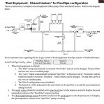
I am following this plumbing diagram for my dual pool/spa setup with spillover and a shared heater. On a Hayward prologic system.

This diagram shows 3 valves.
What is the purpose for valves 1 and 2 exactly?
Is it a trap on each loop to relief pressure from the heater if needed?
Does anyone know which valves should have an actuator?
It looks like there should be a check valve on the spa loop but it’s not in the diagram, would you agree?
 

Attachments

  • Capture.PNG
    Capture.PNG
    49.9 KB · Views: 48
Valve 1 allows the pool water to bypass the heaters and swcg before returning back to the pool, my guess is in case the heaters or swcg need to be repaired or removed. It looks like there are valves in front of each heater as well but they aren't labeled as such.

Valve 2 does the same thing for the spa, allows the water to bypass the heaters and swcg before returning back to the spa.

Can't comment on spa check valve but it couldn't hurt, there is none indicated on the diagram.
 
Thanks for the info. So these should I remain manual valves.
I suppose the only actuator valve in this entire diagram would be what is labeled as valve 3.

I got this diagram from Hayward’s instructions for prologic. My system matches the description of a dual equipment system with one shared heater for both pool/spa.
Unfortunately it’s not descriptive in how each valve should be controlled. I’m going to use this diagram and hope for the best I suppose.
 
Thread Status
Hello , This thread has been inactive for over 60 days. New postings here are unlikely to be seen or responded to by other members. For better visibility, consider Starting A New Thread.