I'm trying to diagnose why my pool lights don't work.
They haven't worked in the year that I've owned the pool.
I have a Compool CP 3600 control panel indoors with a spa side remote. When I activate the lights from either location, the outside panel confirms with it's indicator light that it has recieved the command.
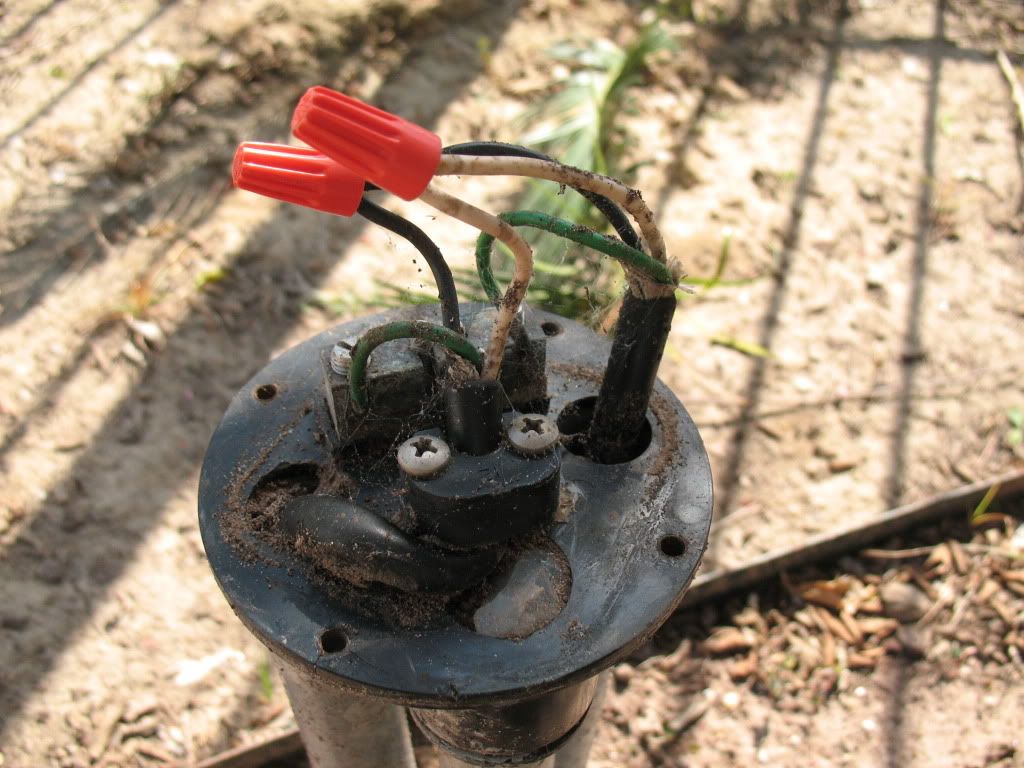
I have 2 locations where 3-1" pvc pipes come into a waterproof cap, and the wiring is connected inside with screw-on caps. I have one located near the equipment pad, and one near the pool deck in a garden. I will report back later today with wiring details.
So far, I can't confirm voltage or even continuity at any of the locations with my multimeter and continuity checker, which leads me to believe there is a problem at the power panel. I opened it up today and there were no obvious wires that were loose or detached. The breakers do show 120V when tested from hot wire to ground rail.
I will be looking at the CP3600 manual to see which way it is usually wired so I know where to look, but I'd really like to know how builders usually set the wiring up, kind of an overview of the entire system.
Pictures/sketches are good, as I'm no electrician by any means and the lingo may be foreign if it gets technical.
I promise I checked the bulbs.
Thanks.
They haven't worked in the year that I've owned the pool.
I have a Compool CP 3600 control panel indoors with a spa side remote. When I activate the lights from either location, the outside panel confirms with it's indicator light that it has recieved the command.
I have 2 locations where 3-1" pvc pipes come into a waterproof cap, and the wiring is connected inside with screw-on caps. I have one located near the equipment pad, and one near the pool deck in a garden. I will report back later today with wiring details.
So far, I can't confirm voltage or even continuity at any of the locations with my multimeter and continuity checker, which leads me to believe there is a problem at the power panel. I opened it up today and there were no obvious wires that were loose or detached. The breakers do show 120V when tested from hot wire to ground rail.
I will be looking at the CP3600 manual to see which way it is usually wired so I know where to look, but I'd really like to know how builders usually set the wiring up, kind of an overview of the entire system.
Pictures/sketches are good, as I'm no electrician by any means and the lingo may be foreign if it gets technical.
I promise I checked the bulbs.
Thanks.