Aqualink OneTouch Control panel with blank screen - pool is new to me

#4 - would like to see a photo of this and the whole equipment pad. It could be an spillover valve to allow the spa to spillover into the pool when the system is in POOL mode.
Thanks!
Three images attached.
When I'm at the house later this week I'll try Aux 2. I have gone through all the buttons but as I was not listening for speed changes, I could have missed it.
 

Attachments

  • PXL_20241204_221321375.jpg
    PXL_20241204_221321375.jpg
    618.8 KB · Views: 6
  • PXL_20241204_221342752.jpg
    PXL_20241204_221342752.jpg
    509.9 KB · Views: 6
  • PXL_20250219_141110771.jpg
    PXL_20250219_141110771.jpg
    850.4 KB · Views: 6
Thanks!
Three images attached.
When I'm at the house later this week I'll try Aux 2. I have gone through all the buttons but as I was not listening for speed changes, I could have missed it.
Thanks for the photos.
On the return to the pool - the actuator is cammed to the partial open position so it is allowing flow to both the spa and the pool at the same time.
The larger diameter pipe to the left with the black check valve is the spa return. They put a check valve on an elevated spa to prevent spa empty into the pool when the pump stops.
The pool has 2 return lines (on the right). The mechanical valve between the 2 lines is open to both so flow is going to both lines. One is the pool returns. Do you have a water feature? If not, there could be 2 separate lines for return to the pool.
I doubt it is going to the spa but don’t want to rule that out. How many returns are there in the pool? Are they all the same level from the surface or are some much deeper then the others?
suggest you rotate the mechanical valve to close one side and see where the flow goes with the other line. Then reverse it.

Some other things to note
On the intake side (suction) - more suction is coming from the main drain then the skimmers. You can rotate that to adjust if you want more suction from the skimmers.
The cover is broken for the electrical receptacle. need to purchase a new one to protect that from the weather.
 
OK... Nothing good to report but I do know more...
First, thanks for the flow chart. I did see that last night when reviewing the 'Further Reading' link you posted and finding the 'Jandy Troubleshooting Manual...' but having it here was quicker.

Disconnected the SPA control panel and tested - No change.
Confirmed that 9.96 volts is available at pins 1&4 at the control box and at the panel location. Also confirmed continuity for pins 2&3/wires 2&3. (Actually, that line is quite nice solid core ~20g wire so pretty tough)
Also tried connecting the remote panel with a short set of leads. Nada... The panel does not do anything but illuminate the amber power indicator.
Correct me if I am wrong but even if the comms chip / PCB are bad, when first powering up, wouldn't the remote panel at least display some sort of initial local boot messages or wouldn't the LCD screen or backlight at least illuminate?
That screen does nothing at all so presuming at least one of those are true then that remote panel must be dead as a doornail...

Here are some pics of the inside:
View attachment 629259 View attachment 629260 View attachment 629261

View attachment 629263
Not sure what it means in the scheme of things yet but based on the dip switches, I gather this is an "older AquaLink board as it does not have the second set of dip switches.
This is what I have:
View attachment 629265

Now... How to proceed...
I still feel like the issue is the control panel(s) and not the comms PCB but perhaps it is both (bummer).

I did not check the voltage on pins 2&3 but even if I do, would that really confirm the comms PCB is working?

If my quick search is correct, replacing the OneTouch panel will be about $600.
I'm not sure if I'm reading it right but I might have a 'L' revision PCB so pretty old. It sort of seems I would need the iQ30-RS kit to move to iAqualink for about $1,200? Money aside, would that be a better solution? It seems more flexible as I gather it can be accessed from iPhone / Android or any HTML5 browser but I do like the idea of just a simple wall mounted panel - guess I could get a cheap Android tablet and mount that to the wall :)
More to the point, would going with that upgrade remove all the known issues I currently have, meaning that would replace the comms chip(s) and give me a working control UI?

Thanks very much for the guidance !!!
If you have checked the price of a new One Touch panel you will jump at the chance to upgrade to an iQ30-RS. It is a completely new board and antenna.
 
Do you have a water feature? If not, there could be 2 separate lines for return to the pool.
Yes, there is a (rather crudely installed) waterfall.
How many returns are there in the pool? Are they all the same level from the surface or are some much deeper then the others?
I am not sure of the answer to either question but I'll confirm when next at the house.
And I will indeed do some valve checks to see what lines are coming out where.
On the intake side (suction) - more suction is coming from the main drain then the skimmers.
That is just coincidental... The photos were taken at different times. There is no pool robo cleaner, so when that was taken, I think we were brushing and trying to get more of the low-lying particles to go to the filter but in any case, I get that...
In fact, I hope that vertical capped pipe between the input and output sections is for a pool cleaner booster pump. It kind of has to be as the only other thing I can think of would be water for a slide but the pool has no deep end so a slide seems unlikely.
The cover is broken for the electrical receptacle. need to purchase a new one to protect that from the weather.
Oh dude... there is soooo much little stuff like that, I cannot even count but I'm slowly working through the list :-Q

Many Many thanks!
If you have checked the price of a new One Touch panel you will jump at the chance to upgrade to an iQ30-RS. It is a completely new board and antenna.
Indeed... iQ30 is on the way :)
 
  • Like
Reactions: HermanTX
OK... iQRS-30 received... The new board and 3.0 antenna are installed, and the antenna is happy with all solid lights. I can ping it on the network so it is clearly on-line but I was stumped. I was hitting the seemingly well-known unrecognized product ID "Enter a valid Device Number" for creating a new location but of all the threads I looked at, the only resolution seemed to be calling Fluidra but of course, that cannot happen until Monday. BUT - It is all on-line now.
My best guess is:
A) It takes some time for the product ID to percolate through the Fluidra cloud database.
B) Some people indicate the system needs to be in Auto to actually connect however I tried multiple times in Auto and in Service mode with no luck.
C) The system needed a proverbial kick 'ReBoot' - I shut all the breakers and restarted everything.
D) The Device Number actually needs to be entered without dashes so xxxxxxxxxxxx and not xxx-xxx-xxx-xxx
Or perhaps it was all the above - I don'tknow but it was very frustrating!

And for those who read this later, yes, the right Device Number is on a label inside the antenna, outside the antenna and printed on the door tag.

Tomorrow I can run through and test things...
 
  • Like
Reactions: HermanTX
The reboot probably was the biggest influence. If you have any issue int he future. It is best to shut down the Aqualink for 1 min or so and then have it come back on line.
Glad it is all working now.
Let us know of any questions on programming, etc.
The first thing to do is to set up the pump.
it would be helpful to update your signature with pump model, filter model. SWCG info, etc.
 
I will update that signature now that I know a bit better what all is there and to that point, a few discoveries and questions...
First, a few pics are attached including a view of the whole pool and SPA.
While Aux 1-4 have connections, only one seems to do anything:
Aux-1 = Blower for the SPA and it works
Aux-2 = I guess would be for a 2-speed motor but all it does is shut the pump off. With further research, it is a Century UST1252 motor which specs say is single speed.
Aux-3 = no clue - I will trace the wires when next at the house
Aux-4 = no clue- I will trace the wires when next at the house
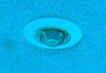
I presume 3 or 4 is for the lights which do seem to exist but they do not currently turn on - more research needed but I have attached a photo of what seems to be a light. I'm guessing it is some sort of LED as the lens is way smaller than what we have in our pool.

Next, the water temp sensor is not reading a temp - the UI reports 'Open' so likely its broken. I started looking around and I have to say, I do not see a temp sensor anywhere on any pipe. I then traced the wire and discovered it leaves the control box and after about 8" ends. No idea where or if there is another half. So I started guessing, perhaps it gets that info from the pool/SPA heater.
I just downloaded the PDF and this is a "Digital" and it seems the control wires run inside the large line that also carries the AC. Something else to look at next time.
The pool heater BTW is a RAYPAK P-R406A-EN-C
 

Attachments

  • PXL_20250322_184436489.MP crop.jpg
    PXL_20250322_184436489.MP crop.jpg
    100 KB · Views: 3
  • PXL_20250322_184535650.MP s.jpg
    PXL_20250322_184535650.MP s.jpg
    553.5 KB · Views: 3
Very nice pool and deck area.
It would be best to take the front cover off and snap some photos of the wiring on lower half and the dip switches on the far left side.
The single speed pump should be connected to the top left relay which is called the Filter Pump relay. Below it is Aux 1 relay.
You must have 2 lights - once each for pool and spa. So they may not be working or not connected properly.
Not sure why Aux 2 would turn off pump unless pump is connected there and not to the Filter pump relay
This the basic layout of a Aqualink layout - the number of relays depends on the model you have.
IMG_0145.png
 
Next, the water temp sensor is not reading a temp - the UI reports 'Open' so likely it’s broken. I started looking around and I have to say, I do not see a temp sensor anywhere on any pipe. I then traced the wire and discovered it leaves the control box and after about 8" ends. No idea where or if there is another half. So I started guessing, perhaps it gets that info from the pool/SPA heater.
Take photos of the plumbing between the pump exit and the inlet of the filter - this is where the water sensor is inserted into the pipework.
 
Very nice pool and deck area.
Thanks - it is a big reason we bought the house - pool construction has really skyrocketed since we built our pool in 2007 but that photo is hiding a rather problematic crack / settlement issue with the sunning deck :-(
It would be best to take the front cover off and snap some photos of the wiring on lower half...
Honestly, whoever did the wiring in there should have their tools taken away or perhaps they had no tools - it's something of a rat's nest so a bit tough to see what is going where.
PXL_20250222_184642148-1500.jpg
And just in my short investigation, I found a wire that was evidently hanging by a strand. Soon as I tugged a bit it came off. Cleaning up in there is on the short list...
As for the dip switches, I just duplicated what the old board had so everything off except #2, which I gather is for a 2-speed motor - which I now know I don't have.
The single speed pump should be connected to the top left relay which is called the Filter Pump relay.
Not sure why Aux 2 would turn off pump unless pump is connected there and not to the Filter pump relay.
I presume the pump is connected correctly as the pump button does turn the pump on and off. It was mentioned earlier in this thread that hitting Aux-2 would put the pump into low speed and I was just sort of guessing that since this is just a 1-speed motor, Aux-2 could disrupt power. I'm presuming there are separate high and low speed connections on a 2-speed motor and high would need to be off for low to work.
Take photos of the plumbing between the pump exit and the inlet of the filter - this is where the water sensor is inserted into the pipework.
The attached shows that area fairly well and I'm quite sure there is nothing hiding on the dark side of that line
PXL_20241204_221321375 crop.jpg
 

Enjoying this content?

Support TFP with a donation.

Give Support
I presume the pump is connected correctly as the pump button does turn the pump on and off. It was mentioned earlier in this thread that hitting Aux-2 would put the pump into low speed and I was just sort of guessing that since this is just a 1-speed motor, Aux-2 could disrupt power. I'm presuming there are separate high and low speed connections on a 2-speed motor and high would need to be off for low to work.
Thanks for the photo and I also went back to Post #8 to try to obtain a better understanding of your wiring.
The pump should be connected to the Filter Pump relay which is the top left relay. However, it appears that the filter pump relay is plugged into the Aux 1 socket (see how each relay is supposed to be plugged into its assigned socket above it) and not the Filter Pump relay. Can you confirm that when you investigate your wiring further? That may be why the Aux 1 turns off the pump.

Agree with your comment that the wiring is very disorganized.
Lights are normally connected to a higher # Aux such as 4 or 5 and they are powered from the GFCI receptacle that protects them and also supplies 120V which some older lights need.

Not sure what that 20amp GFCI CB is connected to as hard to follow wires.

Note - suggest you take a Sharpie and mark what each wire penetration on bottom of the cabinet leads to. This will help in following wires to each CB. The lights may be more difficult to identify since neither is working. My guess is it is unlikely for both to be burnt out so maybe it’s a bad GFCI receptacle or CB that they are connected to for power.
 
I will update that signature now that I know a bit better what all is there and to that point, a few discoveries and questions...
First, a few pics are attached including a view of the whole pool and SPA.
While Aux 1-4 have connections, only one seems to do anything:
Aux-1 = Blower for the SPA and it works
Aux-2 = I guess would be for a 2-speed motor but all it does is shut the pump off. With further research, it is a Century UST1252 motor which specs say is single speed.
Aux-3 = no clue - I will trace the wires when next at the house
Aux-4 = no clue- I will trace the wires when next at the house
I presume 3 or 4 is for the lights which do seem to exist but they do not currently turn on - more research needed but I have attached a photo of what seems to be a light. I'm guessing it is some sort of LED as the lens is way smaller than what we have in our pool.

Next, the water temp sensor is not reading a temp - the UI reports 'Open' so likely its broken. I started looking around and I have to say, I do not see a temp sensor anywhere on any pipe. I then traced the wire and discovered it leaves the control box and after about 8" ends. No idea where or if there is another half. So I started guessing, perhaps it gets that info from the pool/SPA heater.
I just downloaded the PDF and this is a "Digital" and it seems the control wires run inside the large line that also carries the AC. Something else to look at next time.
The pool heater BTW is a RAYPAK P-R406A-EN-C
Those "lights" are fiber optic lens. Somewhere in the yard should be a "tower" about 18" tall and very dark brown or black. If the tower is getting power the most likely cause for no light in the pool is a burned bulb.
 
Not sure what that 20amp GFCI CB is connected to as hard to follow wires.
I've not physically traced the line yet but it does power the post top lamp on the right edge of the pool. There are miles of wire (AC and low volt), conduit and broken / damaged junction boxes throughout the yard so since it powers that lamp, my presumption is that GFCI breaker drives the AC side of all the yard stuff.

The only pool lights I have experience with are the traditional / old-fashioned halogen. I see there are both line powered and low volt pool lights. Would the low volt lights normally be powered from a transformer in the control box or would that typically be placed elsewhere? From what I see in the box, there is only the one transformer for the PCB.

I just partly answered that question, at least about this pool...
I had not looked closely at some of the yard photos taken a while back till now but I now understand that we have a decrepit Fiberstars 6004 or 6004-AS fiber illuminator system.
PXL_20241201_194936184 crop.jpg
Another box to more carefully investigate :-Q
Especially considering the apparent condition of this box, I gather the better alternative will likely be to pull out the fiber and put in some Treo LED lights but I do find the cost disheartening... I hate the idea of being forced to use a specific manufacturers product because of what was previously installed but in this case, if we want in pool lights, there may not be an option. That said, I have fabricated all sorts of LED fixtures - I might be tempted to rebuild the in-pool lenses to house an LED COB if I can make it fit...
 
The only pool lights I have experience with are the traditional / old-fashioned halogen. I see there are both line powered and low volt pool lights. Would the low volt lights normally be powered from a transformer in the control box or would that typically be placed elsewhere? From what I see in the box, there is only the one transformer for the PCB.
Normally there is a separate transformer box for low voltage (such as 12v) pool lights. It can be a significant size so it should be separate next to the automation cabinet.
IMG_8433.jpeg
 
Those "lights" are fiber optic lens. Somewhere in the yard should be a "tower" about 18" tall and very dark brown or black. If the tower is getting power the most likely cause for no light in the pool is a burned bulb.
LoL... I guess our messages passed each other, just above I added more about this:

I had not looked closely at some of the yard photos taken a while back till now. Evidently, we have a Fiberstars 6004 or 6004-AS but it looks very trashed.
PXL_20241201_194936184 crop.jpg
Considering the apparent condition, I gather the better alternative will likely be to put in some Treo LEDs but the cost is disheartening... I've never liked the idea of being forced to use a specific manufacturers product because of what was previously installed but there may not be an option. That said, I have fabricated all sorts of LED fixtures - I might be tempted to rebuild those in-pool lenses to house a COB LED if I can make it fit...
Any idea how big they are inside?
And it seems odd to me that most of the power supplies I see are 12vAC rather than DC, when LEDs, without extra help, are DC devices.
If you have power to the tower, get one of these installed and see if you are happy with the output into the pool.
You can also pull some of the fiber cable out a bit, wrap the end with electrical tape, use a utility knife to cut a small but off and that will increase the amount of light that gets to the in-pool lens. It doesn't actually cut, but breaks off that part revealing a clear path for the light. Those fiber ends get discolored due to the high heat from the bulb.
 
LoL... I guess our messages passed each other, just above I added more about this:

I had not looked closely at some of the yard photos taken a while back till now. Evidently, we have a Fiberstars 6004 or 6004-AS but it looks very trashed.
PXL_20241201_194936184 crop.jpg
Considering the apparent condition, I gather the better alternative will likely be to put in some Treo LEDs but the cost is disheartening... I've never liked the idea of being forced to use a specific manufacturers product because of what was previously installed but there may not be an option. That said, I have fabricated all sorts of LED fixtures - I might be tempted to rebuild those in-pool lenses to house a COB LED if I can make it fit...
Any idea how big they are inside?
And it seems odd to me that most of the power supplies I see are 12vAC rather than DC, when LEDs, without extra help, are DC devices.
Its been at least 20 years since I worked on the lenses of a fiber-optics light, but I believe that they are threaded into fittings with a regular 1.5" pipe thread. If that is the case, any of the available niche-less lights should work if the conduit behind the lens is large enough, though the price and longevity of those lights has proved to be disappointing.
 
Its been at least 20 years since I worked on the lenses of a fiber-optics light ... though the price and longevity of those lights has proved to be disappointing.
Looking at this contraption with 2025 eyes it seems kind of dumb but I have to admit that had I seen one in 1995, I think I would have been pretty amazed.

Anyway, what do you mean about longevity?
As for price, what I am seeing is crazy. Really, a GFCI breaker should take care of things but I can see paying a bit more for whatever might be in a good IP97/98 120>12v power supply as the 120 at least has the potential to be really unpleasant for anyone in the pool but several hundred for a waterproof 12v LED... Really is insane.

And I will definitely consider your note about breaking the end off to get past the old, overheated fiber ends and that lamp is not crazy money but first I need to confirm if anything in that box is salvageable. I'm sure the fan is toast as it's been sitting exposed for I don't know how long. I also suspect that any reflector will probably not be reflective.
I guess the color wheel has/had a motor that drives it? Probably also dead but I don't have the remote anyway...

Thanks!
 

Enjoying this content?

Support TFP with a donation.

Give Support