Aqualink control panel losing power

NewPoolGirlTX

Bronze Supporter
Sep 5, 2021
192
Austin, Texas
Pool Size
13050
Hi all
Electricity question.

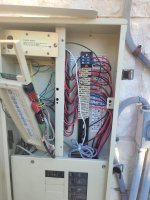
My control panel keeps going dark. It'll work for a day or so and then nothing. When I go look at the panel, no lights at all.

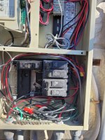
The breakers don't show anything, they are in the on position. If I turn them all off and back on, it comes back online and seems good until randomly it happens again.

I've read the threads about fuses but since it'll work for a good while, I'm assuming no fuses blown

What else would cause this?

If I can't figure it out,
I don't even know whether to call an electrician or pool company.

I'd appreciate any ideas on what to check
 
Does the schedules still run when the panel goes dark or does it basically shut down?
Do you control the equipment via a PDA or via a phone app?
I am thinking the transformer but calling @PoolGate and @ajw22 for suggestions.
 
Do you have a multimeter and know how to measure voltage?

When the panel is dark you need to open it and measure the input voltage to the transformer.

I suspect you have a CB problem. If you don;t have voltage then you have a bad CB. If you do have voltage then you have an Aqualink board problem.

Show us pics of your Aqualink panel and the CB and the inside wiring in the Aqualink cabinet.
 
  • Like
Reactions: HermanTX
Do you have a multimeter and know how to measure voltage?

When the panel is dark you need to open it and measure the input voltage to the transformer.

I suspect you have a CB problem. If you don;t have voltage then you have a bad CB. If you do have voltage then you have an Aqualink board problem.

Show us pics of your Aqualink panel and the CB and the inside wiring in the Aqualink cabinet.
I am not sure I know the terms here. Is CB Control board? is that somehow different than the Aqualink panel?

I have a multimeter but don't fully understand how to use it.

I hope this pic is good enough.

And thank you!
 

Attachments

  • 20231101_164929.jpg
    20231101_164929.jpg
    410.6 KB · Views: 18
You have a Compool system that was upgraded with an Aqualink board.

The blue connector block in the upper right supplies power to the system board. The wires on the right block the label showing how it should be wired for 120V or 240V.

You have circuit breakers at the bottom on the panel. Remove the lower panel to show the wiring at the breakers.

Which breaker controls power to the Aqualink?
 
Last edited:
You have a Compool system that was upgraded with an Aqualink board.

The blue connector block in the upper right supplies power to the system board. The wires on the right block the label showing how it should be wired for 120V or 240V.

You have circuit breakers at the bottom on the panel. Remove the lower panel to show the wiring at the breakers.

Which breaker controls power to the Aqualink?
The wires out of the right side of the blue upper right block go to the bottom two black breaker switches. So far today, it has stayed online.
 

Attachments

  • 20231102_161037.jpg
    20231102_161037.jpg
    440.3 KB · Views: 16
  • 20231102_162619.jpg
    20231102_162619.jpg
    438.9 KB · Views: 16

Enjoying this content?

Support TFP with a donation.

Give Support
Either of those meters will work. I'll give directions for the red digital one as it might be a bit easier to use. Connect the black test lead to the bottom "COM" jack on the meter and the red test lead to the middle "V Ω mA" jack. Turn it on and turn the big rotary switch to the very top "ACV - 750" selection. If the LCD display doesn't come to life and read 0.00 (or similar) then it likely needs a new battery.
When testing be very cautious inside the panel as there are numerous parts that are "hot" and can deliver a nasty shock. Be particularly aware of the large metal bars running under the circuit breakers.
While everything is working put one probe on the neutral busbar, which is that bar on the left where all the white wires are connected, and then at the same time touch the second probe to one of the screws fastening the wires on the suspect circuit breaker. Your meter should read 120 , or something close to that (anything between 107 and 125 is considered normal).

Now that you have the meter figured out wait for it to fail and before doing anything else, check the voltage between the neutral busbar and each of the breaker outputs. If they all read 120 then the problem is probably with the controller card. If however one reads 0, that would indicate the breaker has tripped.

It is not uncommon for old breakers to trip but not move the handle. But turning the breaker to off then on again will still reset it normally.

If the problem is the breaker tripping then some further diagnosis will be needed to figure out what is causing it to trip. It looks like there are at least two controlled loads on the same circuit breaker as the controller itself, I would guess that one is the filter pump, and maybe the second is the pump for the Polaris.
 
  • Like
Reactions: NewPoolGirlTX
It looks like the panel is wired for 240V.

The panel should be tested for 240V with the probes touched to the screws on the upper right blue connector where the wires are connected. Voltage should be around 240V between the upper and lower screw.

One leg of the 240V CB may be tripping which would leave 120V on the circuit and show on a test between the line and neutral bus bar.
 
  • Like
Reactions: NewPoolGirlTX
I should have added to my post: The Aqualink is wired for 120. If you look you'll see the white coming from under the cover where it's transformer is and running down to the neutral bus. The black is tied to one of the two hots for what I would assume is the circuit for the filter and booster pumps. So for checking it's power best to check between the legs and neutral.
 
  • Like
Reactions: NewPoolGirlTX
Ah, I see that now. They wired it for 240V on the right side of the blue connector.

Then they connected to one leg of the 240V circuit for the Aqualink.

I still think 240V should be checked at the right screws of the blue connector to understand what the CB is doing.

I will also note that current codes require GFCI CB for the pump CB for safety.
 
  • Like
Reactions: NewPoolGirlTX
Either of those meters will work. I'll give directions for the red digital one as it might be a bit easier to use. Connect the black test lead to the bottom "COM" jack on the meter and the red test lead to the middle "V Ω mA" jack. Turn it on and turn the big rotary switch to the very top "ACV - 750" selection. If the LCD display doesn't come to life and read 0.00 (or similar) then it likely needs a new battery.
When testing be very cautious inside the panel as there are numerous parts that are "hot" and can deliver a nasty shock. Be particularly aware of the large metal bars running under the circuit breakers.
While everything is working put one probe on the neutral busbar, which is that bar on the left where all the white wires are connected, and then at the same time touch the second probe to one of the screws fastening the wires on the suspect circuit breaker. Your meter should read 120 , or something close to that (anything between 107 and 125 is considered normal).

Now that you have the meter figured out wait for it to fail and before doing anything else, check the voltage between the neutral busbar and each of the breaker outputs. If they all read 120 then the problem is probably with the controller card. If however one reads 0, that would indicate the breaker has tripped.

It is not uncommon for old breakers to trip but not move the handle. But turning the breaker to off then on again will still reset it normally.

If the problem is the breaker tripping then some further diagnosis will be needed to figure out what is causing it to trip. It looks like there are at least two controlled loads on the same circuit breaker as the controller itself, I would guess that one is the filter pump, and maybe the second is the pump for the Polaris.
It finally failed and it turns out the breaker was tripped! I didn't even have to use the multimeter, it showed as tripped. It is the breaker that controls power to the system board.

So i did a bunch of monitoring. the circuit breaker tripped while the main pump and booster pump was running. I tried again and it ran with the main pump for awhile. But once I turned it back on with the booster running as well, it tripped again. Also, the switch for the circuit breaker is hot to the touch.

Does that narrow anything down? what's my next diagnostic step?


I truly appreciate y'all's help so much,
~Marci
 
Main pump amps + filter pump amps gets close to the trip point of an old circuit breaker.

A CB trips earlier as it ages.

I would replace that CB with a GFCI CB.

Show us pics of the filter pump motor data plate and the cleaner motor data plate to see what the pump motor amps are.
 
  • Like
Reactions: NewPoolGirlTX
Main pump amps + filter pump amps gets close to the trip point of an old circuit breaker.

A CB trips earlier as it ages.

I would replace that CB with a GFCI CB.

Show us pics of the filter pump motor data plate and the cleaner motor data plate to see what the pump motor amps are.
I cannot get a pic of my main pump info plate because my equipment is set up stupid and there is no room between it and my sand filter.

So maybe this is the problem? The booster pump is wired for 230. I replaced it in July and spent a bunch of time analyzing how the old one was wired, and pretty sure it was for 230, that's how i determined it how to do the new one (I have a photo of the old wiring if it helps but not the wiring diagram from the old pump motor).

Could that be the problem? Would it run for 4 months ok and then trip the breaker? Is my fix as simple as rewiring the booster pump motor?

And is replacing the circuit breaker with a GFCI CB something I can do myself?

Again, all my thanks guys

(oooh and if it's getting too hot, could it be, that without the metal plates in front of the wiring it wasn't getting too hot? Because I had removed the covers from the wiring and left them off (but closed the box), thinking I'd be testing the CB the next day. But then when it didn't fail, I finally put them back on, and then it failed within a day...!) also though my pool pump motor says 230? This is it Amazon.com and it was put in July 2022. Are both of them wrong?
 

Attachments

  • 20231109_151603.jpg
    20231109_151603.jpg
    339.6 KB · Views: 4
  • 20231109_153614.jpg
    20231109_153614.jpg
    430.3 KB · Views: 4
The booster pump is wired for 230. I replaced it in July and spent a bunch of time analyzing how the old one was wired, and pretty sure it was for 230, that's how i determined it how to do the new one (I have a photo of the old wiring if it helps but not the wiring diagram from the old pump motor).

Could that be the problem?

No.

Would it run for 4 months ok and then trip the breaker? Is my fix as simple as rewiring the booster pump motor?

No.

Your pump motor pulls 10 amps and the cleaner motor pulls 6 amps. The NEC says a CB should be loaded to only 80% of its capacity. That is 16amps on a 20amp CB. You are right at the maximum allowable amperage.

And is replacing the circuit breaker with a GFCI CB something I can do myself?

Possibly.

Your old CB needs to be replaced.

(oooh and if it's getting too hot, could it be, that without the metal plates in front of the wiring it wasn't getting too hot? Because I had removed the covers from the wiring and left them off (but closed the box), thinking I'd be testing the CB the next day. But then when it didn't fail, I finally put them back on, and then it failed within a day...!)

A CB trips based on heat. With your CB at the edge of tolerance putting it in a hot box will lower the trip point.

also though my pool pump motor says 230? This is it Amazon.com and it was put in July 2022. Are both of them wrong?

Both of what wrong?
 
  • Like
Reactions: NewPoolGirlTX
No.


No.

Your pump motor pulls 10 amps and the cleaner motor pulls 6 amps. The NEC says a CB should be loaded to only 80% of its capacity. That is 16amps on a 20amp CB. You are right at the maximum allowable amperage.


Possibly.

Your old CB needs to be replaced.


A CB trips based on heat. With your CB at the edge of tolerance putting it in a hot box will lower the trip point.


Both of what wrong?
I meant are both pumps wrong.

So it sounds to me like the age of my CB is the problem and hopefully replacing it will fix it. I should replace all of them in that box, I assume. I will investigate whether that is something I think I can do, or maybe even see if my father-in-law can help (he was an electrician before an electrical engineer, but he is sometimes reluctant to take on home wiring things).

Thank you again.
 

Enjoying this content?

Support TFP with a donation.

Give Support
Thread Status
Hello , This thread has been inactive for over 60 days. New postings here are unlikely to be seen or responded to by other members. For better visibility, consider Starting A New Thread.