Aqua Logic PS8 not activating valve actuators

TomG

0
Jun 2, 2014
8
Cumming, GA
Hi all,
I replaced my Aqua Logic main board recently and carefully programmed it the way the old one was setup. Everything works great except when switching it to "spa mode", the actuators do not respond.
Each one is getting power and they rotate the proper way when flipping the micro switch in either direction. Did I miss something in the setup of the new board or could it be the new board is faulty? I've read through the manual but can't seem to find anything different to try.

Thanks in advance for any suggestions!
Tom
 
Welcome to the forum!

The micro switch cannot be in the center. It must be on one of the two "on" positions. That determines the controller button on/off direction.
 
Everything works great except when switching it to "spa mode", the actuators do not respond.
I wanted to clarify this statement. Does that mean that when you go to pool or spillover, the actuators do move? Or is it only the suction side actuator which is not moving?
 
I meant that all other functions via the computer (blower, cleaner, waterfall, lights, etc) were operating correctly. There are two actuators...one to switch the spa/pool return to one or the other and the second to switch the
suction side to either the spa or pool. Normally, when selecting spa mode, the pump stops (which it does do now) and then the actuators flip the valves. But again, they are not responding.

I call Hayward support this morning and they want me to have an "authorized" Hayward servicer to come out and diagnose the board to determine if its faulty and if so, replace per the warranty. So I guess I'm faced with having to do
this if the board is faulty.

As there are three wires in the cable that connects the actuator to the board, is it possible that the it can still get power? I need to do a continuity test on each lead to verify the wire is ok.

Thank you!
 
So I assume the valves do not move is spillover mode either?

While spa mode is selected, can you manually switch the valves with the toggle switch?
 
So Hayward required me to have a certified tech verify if the board was bad which he did and now I'm going thru the warranty replacement process. I pulled my new "bad" board out and am putting the old board
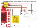
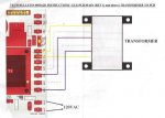
back in so that I can keep my filter going as the tech says it may take a couple of weeks to get a replacement board! When I installed the new board, it came with a Tech Bulletin and wiring diagram (attached) that required changing where certain
wires go. Now that I'm re-installing the old board, I'm unsure what I need to change back (if anything) wiring-wise as I didn't keep a record of how the old board was wired. My old board is PN: G1-066008K-1, the new board is G1-066008N-1 so the vintage doesn't seem that far apart. The tech doc refers to Rev H & J but I can't see anything like this on the board. The wiring diagrams refer to "Rev G and above" which seems to fit with the part nbrs. Does anyone know if they are wired differently?

Thank you!
Tom

pg1.jpg
pg2.jpg
pg3.jpg
 

Enjoying this content?

Support TFP with a donation.

Give Support
Thread Status
Hello , This thread has been inactive for over 60 days. New postings here are unlikely to be seen or responded to by other members. For better visibility, consider Starting A New Thread.