Another one bites the dust. No power to IC40...burned out pins

Indeed. I meant to keep red and black separate. Question, what would happen if you (as an example) cut the pair of red wires and terminate them into a Wago connector and then have a single wire going to (cheap) board connector. The other red wire I would just cut close to connector. Kind of like what @Turbo1Ton did in this picture, except I would leave the connector in place.
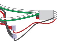
That is the exact fix we devised if the connector is already fried. I illustrated that a while ago, I just didn't show it to you yet, to keep things simple:
IntellipH-Mod-2.jpg

And here's yet another version, if, say, the connector is working, but is showing signs of failure, or if you want to do a preemptive fix that will work even if the connector someday goes out (it won't matter if it does). The only down side to these two fixes is that you can no longer just unplug and swap in a new board, you'd have to do some de-soldering.
IntellipH-Mod-3.jpg
The reason the splices look a little strange is because I illustrated these the way I would splice them. Not with Wagos or wirenuts, and I would not cut the wires at all, rather I'd just strip them, wrap them together with a smaller gauge wire that would then double as the jumper to the circuit board pins. Then I would solder the wraps, to make them corrosion proof, and finally insulate them with epoxy or some other such material.

It's not standard, but it's just the way I do.

Wagos and wire nuts should work fine, but remember, they are just physical connections, theoretically still prone to corrosion and loose connections. For me, soldering eliminates all that and provides the best path for higher current. We discuss Wagos and wire nuts because soldering is something not everybody can or wants to do.

@Turbo1Ton took it one step further and removed the white connector altogether. That's how I fixed mine, too. But he was smart enough to reduce the wire size with Wagos before soldering to the board. I wish I had thought of that! I actually soldered the big fat wires to the board. I would definitely not recommend that. It was a small miracle I got that to work, and taxed my soldering skills to the max!

So there are several ways to skin this cat. All with advantages and disadvantages.
 
Here's my fix, you might have already seen. It's ugly, and I can't believe I didn't fry the traces doing it, but it works, and it eliminates any unnecessary physical connections. @Turbo1Ton's MO introduces 13 physical connections (the Wagos) and I prefer not to do that.

I fixed my board before @ogdento figured out that the reds and blacks connect on the board. I didn't know to connect those first, and so I didn't know I could reduce the gauge of the wire. I plan to someday go back in and do the "off-board splices," to reduce the current running through my board's traces. A project for a rainy day...

intelliph repair 2.jpg
 
  • Like
Reactions: Stoots
Note that only the reds and blacks can connect off the board, and then run as two wires to the circuit board instead of four. That's not so for the whites and greens. They all need to be kept separate, and run individually to their own respective pins on the board. That's why @Turbo1Ton has the two three-way Wagos for the reds and blacks, but has four two-way Wagos for the whites and greens.

My illustrations only show four pins going from the white connector to the board. That's not accurate. There are actually eight pins in that connector, and all eight go to their own hole in the board. The two pins for the two red wires actually connect on the board. Same for the blacks. But the whites and greens don't do that, all four run separately to individual destinations on the board.
 
  • Like
Reactions: Stoots
The reason the splices look a little strange is because I illustrated these the way I would splice them. Not with Wagos or wirenuts, and I would not cut the wires at all, rather I'd just strip them, wrap them together with a smaller gauge wire that would then double as the jumper to the circuit board pins. Then I would solder the wraps, to make them corrosion proof, and finally insulate them with epoxy or some other such material.
Thank you. This is the explanation I was looking for. I can picture this my head. I was just not sure what purpose binding the wires serves. I am not an electrician so I was not familiar with this process.
 
  • Like
Reactions: Dirk
I am not an electrician so I was not familiar with this process.
Ha, neither am I, and no electrician would bother with this rather obscure method (which I pretty much made up), because it would take too long. Wire nuts twist the wires together, but they could still pop free. Wagos kind'a mash the wires up against a metal plate, so the contact surface is somewhat limited. But solder flows into and around every strand of the wire, and in this case the binding wire as well, which makes an unbreakable bond, won't allow any air or moisture in to cause corrosion, and becomes a big slug of conductor that could carry more amps than the wires could.

It's definitely overkill, but that's my middle name. I use this same MO when assembling outdoor low-voltage wiring, which usually lays in the dirt and is subject to all kinds of crud and moisture. I solder all the connections, and then use a special wire nut on top of that to seal the solder slug from moisture. I got tired of tracing shorts and voltage drops, and started taking the time to do it this bullet-proof way. 10 years later and all my garden lights still work perfectly.

If you don't want to deal with the grease I linked, these wire nuts contain a similar goo that protects the connection, whether you solder it or not. They come in different sizes to accommodate the various sizes and number of wires:

 
  • Like
Reactions: Stoots
1719330304452.png

Now this is my replacement from pentair that lasted 4 days. Does anyone know why this keeps happening. My ic40 says it has 20% life left
 
Did it just get plugged in, without the above-mentioned "fix?"

Did you install it? Or was it done by a Pentair repairman?

How many days do you have left on your warranty?
 
Quick update. PB ended up swapping out the controller for a new one under warranty. Let's hope this next one lasts a little longer. Next May I may just perform this rewire right before end of warranty.
 
  • Like
Reactions: Dirk
Thread Status
Hello , This thread has been inactive for over 60 days. New postings here are unlikely to be seen or responded to by other members. For better visibility, consider Starting A New Thread.