Hello Friends, need help with a non-functional MT400 heater.
I've searched online and might have missed somewhere that addresses this specific issue.
Info
- Inground pool built in 2016, Pentair equipment. As mentioned, MT 400 natural gas heater
- Using the Intellicenter with EasyTouch controller, no phone app installed.
Issue
- Sudden failure of heater not igniting, no blower either. Everything worked fine about a month ago.
Observations
- When SPA is selected on the Easytouch controller, both auto valves rotate normally from pool to spa settings
- VS pump changes speed as it has done in the past
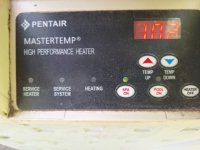
- Heater control panel goes through what I believe is a self-check, shows the current software (R13 I believe) and then reverts to the selected heat setting on the panel. This is different from prior where it would indicate the current (before-heating) spa water temperature. I can manually select up or down on the panel to change that number. Before, I could simply observe a steady water temp increase reading on the panel as the spa began to heat.
- No warnings on the membrane touch panel (service system, service heater, etc.) just a green led showing heater on. However, the service system/heater led's do light initially, again, I assume as part of the first start self-test.
- No green "heating" led showing on the membrane touch panel
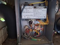
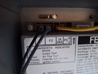
- Control board has no warning led's lit on the back, just the green operating led.
- Upon initial SPA selection, all red leds on the back of the board light up momentarily, then are dark, I believe this to be part of the initial self-check.
- When SPA has been selected, other than the valve position changing, nothing happens at the heater, no blower, no gas on, no ignitor, all dead.
- When SPA selected, I cannot switch between pool and spa on the panel, just stays in spa mode, maybe this due to the Intellicenter controlling the heater? I have not tried the V (Valves) setting at the Intellicenter itself.
- These results are the same whether I select SPA on the EasyTouch or at the Intellicenter panel.
- I've attached a picture at the molex connector from the membrane pad to the control board. I'm not sure but it almost looks like a transistor (?) may be burned at J6-6 circuit? But I also see some other darkened components, I'm not sure.

What I've done
- over the past several years I've addressed stuff like short-cycling, flue gas, water flow switches etc. The heater has generally run fine and I keep the pool filters clean. I have a general understanding of the guts of this thing.
- A couple of years ago I changed out the membrane pad on the heater
- checked that gas inlet valve and gas valve are on
- verified 24v out of secondary transformer
- verified main power to the heater and to the ignition module and related connectors at the power box inside the heater
- verified continuity on both sides of a glass fuse at the firemans switch
- verified heater-related connectors are ok at the Intellicenter board in the panel itself
- verified wire integrity inside the heater itself, no frayed/chewed wiring
- verified that there are no red trouble leds lit on the back of the control board. Since they all cycle initially I figured that they are operational.
- unplugged membrane connector at control board, jumpered J6-5 to J6-6 to see if heater would activate, nothing.
- Even though no trouble led's were lit, I jumpered a few of the switches, such as flow, flue gas, etc just in case they impacted this no-heater issue, no change at all.
Any help would be appreciated; I'm suspecting the control board but wanted to ask more knowledgeable folks first.
thanks!
I've searched online and might have missed somewhere that addresses this specific issue.
Info
- Inground pool built in 2016, Pentair equipment. As mentioned, MT 400 natural gas heater
- Using the Intellicenter with EasyTouch controller, no phone app installed.
Issue
- Sudden failure of heater not igniting, no blower either. Everything worked fine about a month ago.
Observations
- When SPA is selected on the Easytouch controller, both auto valves rotate normally from pool to spa settings
- VS pump changes speed as it has done in the past
- Heater control panel goes through what I believe is a self-check, shows the current software (R13 I believe) and then reverts to the selected heat setting on the panel. This is different from prior where it would indicate the current (before-heating) spa water temperature. I can manually select up or down on the panel to change that number. Before, I could simply observe a steady water temp increase reading on the panel as the spa began to heat.
- No warnings on the membrane touch panel (service system, service heater, etc.) just a green led showing heater on. However, the service system/heater led's do light initially, again, I assume as part of the first start self-test.
- No green "heating" led showing on the membrane touch panel
- Control board has no warning led's lit on the back, just the green operating led.
- Upon initial SPA selection, all red leds on the back of the board light up momentarily, then are dark, I believe this to be part of the initial self-check.
- When SPA has been selected, other than the valve position changing, nothing happens at the heater, no blower, no gas on, no ignitor, all dead.
- When SPA selected, I cannot switch between pool and spa on the panel, just stays in spa mode, maybe this due to the Intellicenter controlling the heater? I have not tried the V (Valves) setting at the Intellicenter itself.
- These results are the same whether I select SPA on the EasyTouch or at the Intellicenter panel.
- I've attached a picture at the molex connector from the membrane pad to the control board. I'm not sure but it almost looks like a transistor (?) may be burned at J6-6 circuit? But I also see some other darkened components, I'm not sure.

What I've done
- over the past several years I've addressed stuff like short-cycling, flue gas, water flow switches etc. The heater has generally run fine and I keep the pool filters clean. I have a general understanding of the guts of this thing.
- A couple of years ago I changed out the membrane pad on the heater
- checked that gas inlet valve and gas valve are on
- verified 24v out of secondary transformer
- verified main power to the heater and to the ignition module and related connectors at the power box inside the heater
- verified continuity on both sides of a glass fuse at the firemans switch
- verified heater-related connectors are ok at the Intellicenter board in the panel itself
- verified wire integrity inside the heater itself, no frayed/chewed wiring
- verified that there are no red trouble leds lit on the back of the control board. Since they all cycle initially I figured that they are operational.
- unplugged membrane connector at control board, jumpered J6-5 to J6-6 to see if heater would activate, nothing.
- Even though no trouble led's were lit, I jumpered a few of the switches, such as flow, flue gas, etc just in case they impacted this no-heater issue, no change at all.
Any help would be appreciated; I'm suspecting the control board but wanted to ask more knowledgeable folks first.
thanks!


