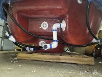
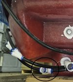
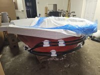
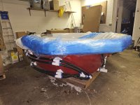
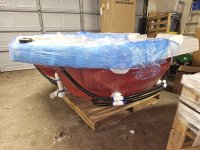
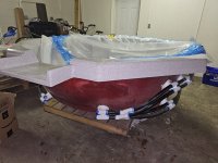
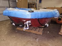
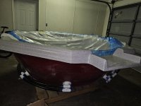
Thank you a lot. If you mean the schematic of the return 1" pipe, below are better pictures that go all around the spa (use the yellow measuring tape as reference for the pic angle).
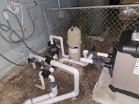
I meant for the entire plumbing system. All pipes, fittings, valves, equipment and distances between them.
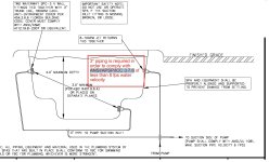
Basically, I will have 3" draining line from the equipment (starting at the junction of the two pre-plumbed 2" drain pipes), 2" pipe through the equipment and 2" back all the way to the junction where 1" pipes bring water to the 10 jets (see black circle in pic below).
I would upsize those to at least 2.5". I am surprised that the city did not flag that because I believe Florida follows APSP-7 regulations for 3 ft/sec.
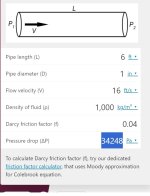
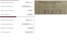
As for the head, you are right I neglected the head loss on the 1" pipes and just shove it inside the 4' of miscellaneous head drop because I thought it was short. Also I am more conservative by neglecting it (like I am overestimating max velocity by neglecting it), since if for instance the head drop was 70 feet, then the flow rate would be 115 GPM and the drain velocity would be smaller. I can compute an (over)estimate of head loss on those pipes feeding the jets by considering two 1" pipes departing at the junction in the black circle below, each carrying half flow rate, and they are ~6' long. Using
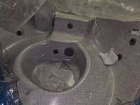
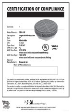
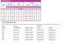
this calculator, for a Re=4000 (Darcy Friction factor for PVC of 0.04) I get 11' of head drop (34248 Pa). That would change little with different Re, I kept it simple. That seems highly overestimated, since in reality those pipes form loops with 10 pipes. Also, I shove in those miscellaneous losses also the exit losses of the jet. I have a 3/4" nozzle size, that gives an exit loss (using velocity/(2*gravity) and flow rate of 140/10=14 GPM for 1 out of 10 jets) of 1.6'. See pic of the drain specs, each drain is good up to 160 GPM. See at the end of this post below the list with all the losses I have considered.
You need to make decisions based upon realistic numbers. What you are calculating is not realistic.
First, a Reynolds number of 4000 for 1" PVC is a flow rate of 1.4 GPM so I am not sure why you were using that.
Next, the 3/4" outlet you are seeing is the external eyeball and not the internal jet nozzle. Here is an illustration of a typical venturi jet:

The jet nozzle is embedded in the venturi tee. The schematic in the first post says 8-10 GPM per jet which is consistent with 5/16" jets. So you won't need more than about 100 GPM although it doesn't hurt to have the potential for a little more.
My questions are:
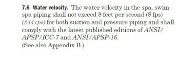
1) Is it a problem if the 2" return pipe exceeds 8 fps? Would you do 3"? See screenshot below of ANSI/APSP/ICC 3 7.6. Why does it say " 8 ftp both suction AND pressure piping"? Does pressure piping mean "any pipe"? Why should the speed in the return pipe be limited? There is no entrapment issue there. Is that for energy efficiency?
Yes, I would use 3" pipe. You don't want extra head loss for a spa or the jets will be very weak (see analysis below). The speed within a pipe is not limited by anything. The 8 ft/sec is a recommendation to keep head loss low for higher efficiency and the possibility of water hammer low to prevent plumbing failures.
2) The math above is done just to be safe when the max speed of the pump (3450 rpm) is turned on by mistake on the spa. That max speed is only used for the pool when using the robot vacuum (POOL mode, no water recirculation in the Spa). Instead, the spa operational rpm that I would set up on Omnilogic when in SPA mode would be 2350 rpm, or slightly above if I underestimated losses, and it would give a flow rate of 80 GPM, which gives just 4 fps velocity on each drain. I do think that spa has to be designed for max speed rpm, i.e considering that some one by mistake sets up the pump to his maximum rpm. But I think we are pretty safe about entrapment with ~2350 rpm. Do you agree?
Perhaps but again, the numbers you are calculating are not realistic. In most cities, to pass inspection, they base the entrapment flow rates on maximum speed because they do not know how you will use your system.
3) You say "For entrapment safety (VGBA), each main drain line should be below 6 ft/sec when the other is plugged which means that each line of the MD pair needs to be below 3 fts/sec when operating together.". Can you point where it says it is enforced for residential? I did not see it in the ANSI
4) You said " after the MD TEE further up stream 8 ft/sec is allowed in the suction line although not recommended due to high head loss conditions under high flow." I guess you meant downstream, right?
VGBA is a federal statute and applies to both residential and public pools. Each city has different rules and sometimes they can be more stringent than federal or state regulations so you should check with your local building department.
There is also APSP-7 which is often sited in federal, state and local regulations:

Losses I Considered:
- 60 ft of drain line at 3" and 0.07 ft/ft gives 4.2 feet of loss
- 60 ft of return line at 2" and 0.07 ft/ft gives 9.5 feet of loss
- heater loss (0.002*Q_GPM^2): at 140 GPM gives 39.2
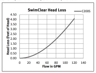
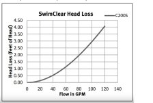
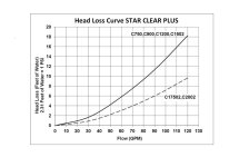
- the filter loss (1.4 feet),
- 4 feet for miscellaneous losses (bends, exit losses, 1" return loops etc, probably it is more than 4 ft)
Total loss: 57
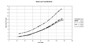
I don't think any of that is correct except for the heater. That is the same equation I use for my analyses. The fittings will account for much more head loss that what you are suggesting. Also, a cartridge filter is about half the head loss of the heater. Where did you get that number? I have some actual filter head loss numbers in this sticky:
Edit - Before reading this article, you may want to first familiarize yourself with this Pool School article on Pump Basics Hydraulics 101 - Pump Head Curves, Plumbing Head Curves and Operating Points Hydraulic Head In fluid dynamics, head is a concept that relates the energy in an...

www.troublefreepool.com
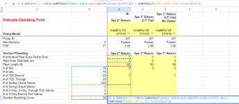
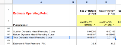
Also, I have several spreadsheets that I make available to the forum specifically for this type of analysis. Based upon what you have told me so far, and quite a bit is still missing so I will need to guess, I have pre-populated the spreadsheet to come up with a more realistic view of your setup. You can review it here in Google Sheets:

docs.google.com
We can make adjustments with new information.
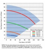
The operating point that I come up with for your current setup @ 3450 RPM is 91.41 GPM @ 85.4' of head.
Changing the return pipe to 3" and the pad pipe to 2.5" results in an operating point @ 3450 RPM of 97.5 GPM @ 83.2' of head.
Both designs actually fall short of the 100 GPM target. But if you can find the manufacture recommendations, we may be able to make some adjustments such as bypassing the heater. This will change the 3450 RPM operating point to: 108.1 GPM @ 79.2' of head.
Note for all of these cases, the velocity in the 3" pipe is well below 6'/sec and even in the 2" case, it is close to 8 ft/sec.
More spreadsheets:
Edit - Before reading this article, you may want to first familiarize yourself with this Pool School article on Pump Basics Hydraulics 101 - Pump Head Curves, Plumbing Head Curves and Operating Points Hydraulic Head In fluid dynamics, head is a concept that relates the energy in an...
www.troublefreepool.com