Two Speed Motor control Electric Hi/Low Speed timer switch.

bobodaclown

TFP Expert
LifeTime Supporter
Apr 14, 2011
2,355
Murrieta, CA
Hello All,
Currently running a 3/4 HP 2-speed 115V motor. I'm interested in running high for 1/2 hour to an 1 hour on high speed then rest on low. High for better skimming action. I move approx. 45 gpm on high and 22 on low.

I've purchased a DC12v Multifunction Delay Timing on/off Optocouple Relay Module 30A Switch Timer
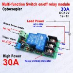
s-l1600.jpg

I've bench tested it, and it will work mechanically for what I want it to do.
When 115V is applied (from T101) timer it will power a 115V-12Vdc converter to DC 12V, and will also supply trigger signal, closing the relay switch (NO on) High speed will be on. Timer will be set for 1 hour to begin. When it times-out, relay goes back to NC (Low Speed), until the T101 Switches off.
I'm hooking High Speed to the NO contact and Low to the NC contact. COM will have the 115V from the output side of the the T101.

It will be housed in a 6 X 6 X 3 box with the 120V to 12V transformer. Weatherproof Electrical Enclosure Box Plastic NEMA 4 Clear Lid 6 3/4"x6 3/4"x3"
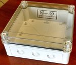
box.jpg


I think I'll have $25 in parts into it.
 
Hello All,
Life happens, still getting things setup.
I've bench tested the relay. Works as I had hoped.
I think I'm going to do a 5 minute High speed run time basically to prime then switch to low. Pump normally primes in less than a minute.

When power is applied, I'm running a jumper wire from the power supply to the trigger, relay goes on (high), timer counts down/removes power goes to low speed.

I'm looking at adding a 3-way switch that will allow override of the timer to allow for high speed only operation to be used when vacuuming or when I have water features going.

I'm attaching a wiring diagram. Please comment if you thing I might improve on it. Thank you.
pool relay wiring diagram.jpg
 
Assuming you left out the 12v power supply between the switch and timer input, your wiring diagram looks correct. Since the timer module is actually a form C relay, backfeeding power into it won't hurt anything.
 
Hi Bama,
This is a 120V motor not 220V not sure it that mattered, but wanted to confirm.

I thought of that, I think, that's one reason for the 3-way switch (only one leg is live at a time). Maybe the red wire color should be different.
1. When Bypass timer on at the 3-way switch the blue wire is live (Timer Enable dead), pump is running Hi speed. (Timer Enable is dead) The relay is connected to Low speed, no power on COM connected to Normally Closed (low speed) contact/no power on COM/Low, the Normally Open (High speed) contact has power pump is running.

2. When timer enable selected at 3-way switch. Initially blue wire is dead, red wire Com/NC (low) are connected through Normally Closed relay. When power is applied, power is on Common, relay is energized, closing contact (High energized) pump running high speed. When high speed is energized, the blue wire is live, even at the 3-way switch. Relay timer counts down, relay power is removed, Normally Open (High speed ) contacts switch to Normally Closed (low Speed). Blue wire is dead. Pump is running low speed.

Looking at the picture of the actual relay, there will be one wire on COM (120V) and NC (low), and two wires on the NO(high) (one going to motor and one going to 3-way switch).

"The critical part of the diagram missing is the power going into 'COM'." Only time power is going into COM is when the 3-way switch is in timer enable.
"When the timer is de-energized power is going into the Com terminal and out the the N.C. terminal." That is correct, pump would be running on low speed.
"If you put power to the high speed input of the pump with the jumper, it will have power to both high AND low speed winding. Not good for the motor!" I would agree with that, but the "jumper" receives power through the 3-way switch. It provides power to jumper or the COM on the relay not both.

Looking forward to reply to my reasoning. Thanks for the discussion.
 
Hello All,
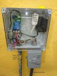
I've connected it, tested, cycled, and it's working as designed. The addition of the timer allows the pump to prime on hi, then switch to low speed operation. (time is adjustable from 1 sec to 60 minutes)
The system initially had a Hi/Low switch only, that has been replaced by the relay, that goes to hi speed for 1 minute then low. I've added the option to operate in hi speed only also through the use of a 3-way switch.

Power comes from a T101 Intermatic timer, the power then goes to a three way switch, it allows for operation of the timer or continuous hi speed operation. In the alternate position, it enables the relay and low speed operation (after the specified hi speed operation).

The initial 3-way switch take 1 input (power and allows two outputs A or B). Output A goes directly to High speed operation, Output B goes to the Relay. The relay is set so Hi speed is on the Normally Open (NO) position. The only time the NO contact are closed is when power is applied to the relay, an then it's only closed for a limited amount of time. The Normally Closed (NC) position is used for low speed.

Power cannot be applied to NO/NC contacts at the same time, unless there is a massive failure internal to the relay.

labeled Relay Panel Low.jpg
 
Thread Status
Hello , This thread has been inactive for over 60 days. New postings here are unlikely to be seen or responded to by other members. For better visibility, consider Starting A New Thread.