Detecting if a pump is actually running?

mShark

Silver Supporter
Jun 5, 2024
102
San Marcos, Texas
Pool Size
10000
Surface
Plaster
Chlorine
Salt Water Generator
SWG Type
CircuPool RJ-45 Plus
I don't know about you, but Murphy and his laws are never far from me. If it can go wrong, it likely will. In my case I have moved from a single speed pump to a VSP. Previously the SWG was wired to the timer with the pump so that it could never get power without the pump getting power. The VSP has constant power to run the programmed schedule so the SWG loses that little bit of protection and must rely on the flow switch entirely.

I could do this easily with various wifi enabled devices but that adds opportunities for Murphy to have fun with me.

AC current measuring switches are available with adjustable set points. I can connect the switch to a 2 minute time delay then to a relay powering the SWG. Adjust the setpoint to trip at the lowest speed/current I need for the SWG. The time delay gets it past any priming issues. I hate seeing my SWG flashing all the lights while the flow switch is dealing with pump startup.

Does this make sense?
 
I do not see a reason for a time delay or priming issues with powering the SWG when the pump power trips the relay.
 
I do not see a reason for a time delay or priming issues with powering the SWG when the pump power trips the relay.
That is the beauty of the CSR. Even if the power is available to the pump, if the pump is not running (for whatever reason), the CSR kills the power to the SWG.
 
It appears from the schematics and devices referenced in a previous post are switching one leg of the power to the SWG. Are the SWG's running at 120 volts?
 
I run my SWG on 120. First picture shows the wiring. You want to do at least 2 loops with 120. You have to set the current trip based on your pump speed. I think my is down around 15% because I run my pump on low speed. This is the CSR for 120... https://www.crmagnetics.com/Assets/ProductPDFs/CR4395 Series Catalog Page.pdf

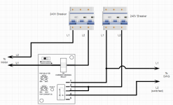
If you want to run 240, see second pic.

Plumb 2.jpg


This is 230. The diagram only shows one pass-through of the L1 line through the current sensing coil, but you are going to want to loop it through at least four times. With four loops, the current sense range is reduced to 0.5 to 5 amps. With a variable speed pump, you will run at the lowest speed that still pumps enough flow to close the SWG's flow switch. At these low speeds, you will not be pulling much current, so getting the trip range low will give you some room to use trip current adjustment. Try to get a couple of more loops through it. Six loops will give a range of 0.33 to 3.33 amps. This is the same trip range that most use with VSP, and 4-6 loops and 20% seems to work. The selector switch in the top left-hand corner is to be slid over to the left, selecting overcurrent. For 230, you want something like this: 230 CSR
1737817944027.png

If you have separate breaker for SWG:
1737818769805.png
 
Last edited:

Enjoying this content?

Support TFP with a donation.

Give Support
Thank you. I'm ordering parts this weekend to get this done. Do you have the swg on a gfci breaker?

Another thing I need to fix is adding a power cutoff switch for my pump. The pump pulls too much power to go through my switch and the breaker is on the other side of the fence. Should I add a sub-panel or is a double pole switch fine?

Last, when I bought the whip assembly at Lowes for the power it had 10 gauge wire which the "experts" said I needed for the 3 hp motor. It is rated at 10 amps and is on a 15 amp breaker. 12 gauge should be fine and actually be workable, right?
 
Thank you. I'm ordering parts this weekend to get this done. Do you have the swg on a gfci breaker?
In some parts of the United States and Canada, the Control Module must be connected to a circuit protected by a Class A ground fault interrupter (GFI). Check local codes before connecting.
Pump should be on a GFCI.

Another thing I need to fix is adding a power cutoff switch for my pump. The pump pulls too much power to go through my switch and the breaker is on the other side of the fence. Should I add a sub-panel or is a double pole switch fine?
Get a service disconnect rated for your application. This one may not be the right one for what you are doing, but this is a disconnect.

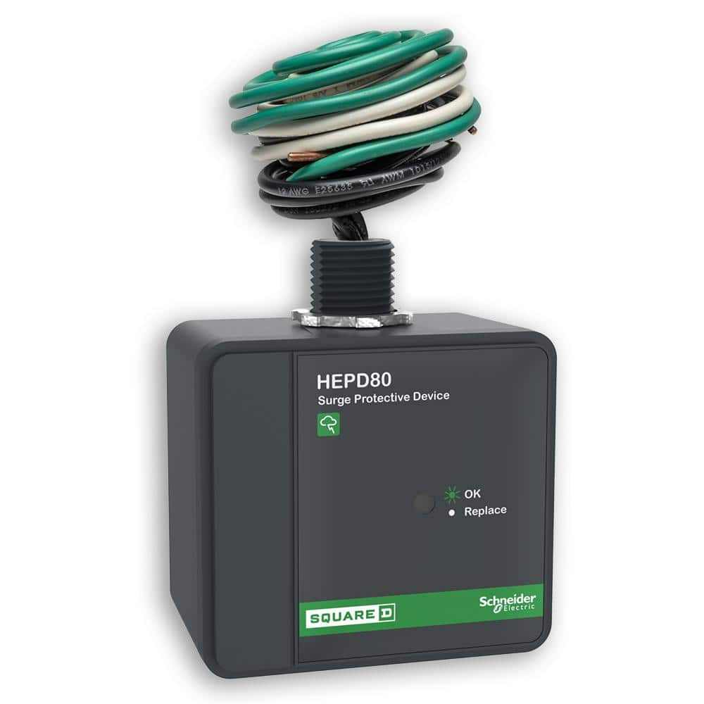
Pro-tip #1 : Whatever sub-panel/service disconnect you are going to use to power to the pump, I highly suggest you put a whole-house surge protector on the panel like this one

Last, when I bought the whip assembly at Lowes for the power it had 10 gauge wire which the "experts" said I needed for the 3 hp motor. It is rated at 10 amps and is on a 15 amp breaker. 12 gauge should be fine and actually be workable, right?
The terminal block connections are capable of handling up to 12AWG. Per NEC, should be stranded. Choose a wire size for the pump in accordance with the current National Electrical Code and all applicable local codes and ordinances. When in doubt use a heavier gauge (larger diameter) wire. Be sure the wiring voltage is within the operating range. You should be fine on 12 gauge stranded.
 
  • Like
Reactions: mShark
The terminal block connections are capable of handling up to 12AWG. Per NEC, should be stranded.
Solid or stranded should not matter unless the terminal is only rated for one type.

What does matter is how the wire is connected to a screw terminal. Solid wire can be inserted straight on one side of a screw terminal and tightened down.

Stranded wires should always be looped clockwise around a screw and tightened down. Or a ferrule connector should be crimped on the stranded wire.

Stranded wires is more flexible and easier to pull. Solid wire makes a better connection with screw terminals and is less likely to lossen over time.
 
Last edited:
  • Like
Reactions: mShark
MTW rated stranded wire should always be used around motors and equipment where there is vibration. Except for the grounding wire.

I agree on the connection and prefer crimped wire terminals.
 
Currently both the pump and SWG are on the same gfci breaker, primarily because it ran when the pump did. I will be adding a circuit for the SWG. Thanks for reminding about the service disconnect. It is a reliable solution, too. I've got an 80KVa whole house arrestor installed already. Thanks for the confirmation on the wiring. I've got both ferrules and crimp terminals, so options. Did you mount the current sensing switch in a duplex size box, or something bigger?
 
  • Like
Reactions: mShark
20250205_142322.jpg
Finally installed the current sensor and have it working. I could only get 5 passes through the core with the 12ga stranded wire I used. You can see the detect level is at the low end of the adjustment. If it gets funky on the detection for any reason then I may change to 14 ga and get a few more turns. It has been very reliable once I set it up. The detection occurs around 800 rpm now. Thanks for the guidance in getting this working.