Prologic Relay Wiring - SWG (RJ-60)

RedSkip

Member
Apr 25, 2021
17
Sienna Texas
Wanted to reach out and see if my thought process is correct, appreciate your time in advance.

Question: When wiring a SWG to 120V from the pump relay, is it safe to assume that the 2nd and 4th wiring terminals are the "load/out" side of the relay and the 1st and 3rd terminal lugs are the "Line/in" side of the relay? If so, my thought process on wiring goes as follows:

1. SWG White to the Neutral Bus
2. SWG Black to the 2nd or 4th Terminal Lug since the pump is wired for 240V.
3. SWG Ground to the Ground Bus

Seems pretty straight forward, but wanted to ask prior to installing. Open to feedback/criticism in my thinking...

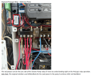
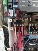
Hayward ProLogic Relay - Reference Photo
Relay wJumpers.jpg
The red jumpers are for the Line side of the Cleaner Pump relay if I have my understanding right on the ProLogic relay operation.
Side Note: The original installers used White/Black for the Load power to the pump to achieve 240V, not Red/Black.

Skip
 
Skip,

Why not just wire the SWCG for 240???

Is the Circuit Breaker that powers the Pump/Filter relay a GFCI breaker or not??

Thanks,

Jim R.
Hi Jim,

Didn't think of wiring it for 240V, I assume the logic is the same as mentioned above but utilize both sides of the "Load/out" on the relay. I don't believe the breaker is GFIC, there is no "test" button on the breaker itself.

Edit:
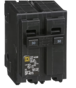
The breaker is a Homeline, DP-4075 30A, I don't believe it's a GFIC from my quick research...

Skip
 
Last edited:
Skip,

If the breaker were a GFCI breaker, and you wired it like you wanted, it would pop the instant you turned on the SWCG... :mrgreen:

Wiring the SWCG for 240 VAC, seems to me the best approach.

The 240 for the SWCG would come from the Load side (pins 2 and 4) of the pump/filter relay..

Thanks,

Jim R.
 
e 240 for the SWCG would come
Skip,

If the breaker were a GFCI breaker, and you wired it like you wanted, it would pop the instant you turned on the SWCG... :mrgreen:

Wiring the SWCG for 240 VAC, seems to me the best approach.

The 240 for the SWCG would come from the Load side (pins 2 and 4) of the pump/filter relay..

Thanks,

Jim R.
Cadillac, thank you kindly!
 
You should install a GFCI CB for safety and wire the SWG for 240V.
 
You should install a GFCI CB for safety and wire the SWG for 240V.
Is it safe to assume the follow if I were to install the GCFI CB myself?
1. Pump Neutral to CB
2. Pump Ground to Ground Bus
3. Hot (2) to the CB
4. Neutral from CB to Neutral Bus

For the SWCG that only has 2 hots and ground:
1. Hot1 to Pump Relay - Load 1 (2nd terminal block on relay)
2. Hot2 to Pump Relay - Load 2 (4th terminal block on relay)
3. Ground to Ground Bus
4. Ground from Controller to Earth Ground

Skip
 
240V pump does not have a neutral.

You do not connect controller ground to earth. Grounds connect to electrical panel ground only.
 

Enjoying this content?

Support TFP with a donation.

Give Support
1711136181529.png


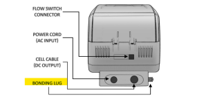
Bonding:

A lug used for bonding is attached to the bottom of the RJ-Series Control Module.

The Control Module must be bonded with an 8 AWG copper wire to the pool bonding system.

One bonding lug for US models is provided on the external surface.

To reduce the risk of electric shock, connect the local common bonding grid in the area of the swimming pool, spa, or hot tub to these terminals with an insulated or bare copper conductor not smaller than 8 AWG US.
 

Attachments

  • CircuPool-RJ-Manual.pdf
    1.9 MB · Views: 0
Is it safe to assume the follow if I were to install the GCFI CB myself?
1. Pump Neutral to CB
2. Pump Ground to Ground Bus
3. Hot (2) to the CB
4. Neutral from CB to Neutral Bus

For the SWCG that only has 2 hots and ground:
1. Hot1 to Pump Relay - Load 1 (2nd terminal block on relay)
2. Hot2 to Pump Relay - Load 2 (4th terminal block on relay)
3. Ground to Ground Bus
4. Ground from Controller to Earth Ground

Skip
Edit: All, sorry for typing/speaking poorly, I was at an appointment today and typing on my phone in the lobby.

The SWCG is already hooked up and running. There was a comment in the thread that if I connect the SWCG to a GFCI breaker like I have it wired today, it would trip the breaker immediately.

I’m not against wiring the GFCI and upgrading the breaker, but I want to avoid the constant tripping of the breaker.

Skip
 
Is your SWG wired for 120V or 240V.

The comment was based on the SWG being connected with 120V.
 
SWG White to the Neutral Bus
If you wanted to wire 120, then you use the neutral lug on the breaker to connect a neutral from a 120 volt applicance.

The breaker is a Homeline, DP-4075 30A, I don't believe it's a GFIC from my quick research...
It is not GFCI.

Also, 30 amps is too big for that breaker.

You should use a 20 amp GFCI breaker.

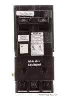
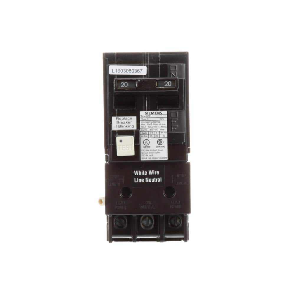
20 Amp Double Pole Type QPF2 GFCI Circuit Breaker by Siemens.

Why didn't you just get a T-15 cell and plug it into the ProLogic?

1711138859235.png


20 Amp Double Pole Type QPF2 GFCI Circuit Breaker by Siemens.

1711139086654.png


1711139238552.png
 
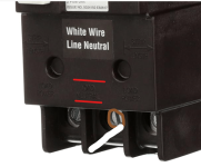
By connecting to the Breaker neutral, the GFCI can account for the current on the neutral line.

The neutral current goes through the breaker and through the breaker white neutral line to the neutral bus bar.

In any case, you are wired for 240, so it should be fine.