Automation upgrade for Jandy RS8 for Intelliflo3 VSF pool pump

Pcnef

Member
Jan 19, 2024
9
Dallas
Hello,
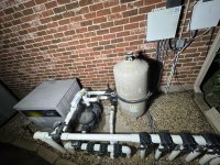
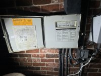
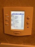
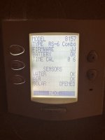
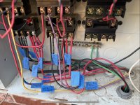
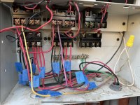
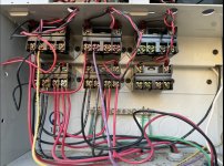
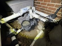
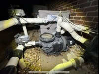
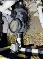
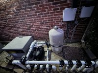
I have Jandy RS6 Automation system with a single speed HP 2.0 pump running a pool/spa combo with an old hayward Northstar pump. This controls the pool and spa control, blower control, spa and pool light control. See pics. I want to change my pool pump to variable speed pump using the Intelliflo3 VSF (011075 or 011076). I am aware that my automation system is dated and I want to make sure that I have everything I need to make my pool and spa work with all current functions listed above. I currently have a PDA inside my house and I control my pool/spa functions through this and I also program it through the PDA. I like the idea of having controls on my phone or computer and want to upgrade if costs reasonable. I did some research about methods of upgrading my current system. I saw the older IQ9000 and the newer IQ30-RS ($1000) Upgrade which I read will work on my dated system, but not sure if intellioflo3 will work.

I would like to connect my variable speed pump (intellioflo3 VSF 3HP with possible. I/O board) and be able to control the pool, spa, blower, pool and spa lights and new VS pump speed.

Can I do that with my current configuration? Do I need to upgrade to IQ30-RS to do that? The pool company I contacted told me I need to get an intellicenter control to work an intelliflo pump but this is an expensive route. I ready otherwise. I want to be sure the system will work before i purchase parts. i would like to do this DIY if possible. Please if you have any advise as to where I can get required parts cheaper, please let me know.

Thanks in advance for your input and recommendations.

Patrick
 

Attachments

  • IMG_4114.jpeg
    IMG_4114.jpeg
    627.1 KB · Views: 5
  • IMG_4115.jpeg
    IMG_4115.jpeg
    504.1 KB · Views: 6
  • IMG_4119.jpeg
    IMG_4119.jpeg
    428.8 KB · Views: 5
  • IMG_4120.jpeg
    IMG_4120.jpeg
    350.9 KB · Views: 7
Welcome to TFP.

Your RS6 REV JJ cannot control VS pumps. You need at least REV O.

The IQ30-RS upgrade will give you VS pump control along with iAqualink.

Aqualink can then control the basic VS control of Intelliflo pumps but not use other advanced features of the IntelliFlo3 like the VF control.


BTW, I dumped my old Aqualink system and replaced it with an IntelliCenter. It is a much better system that gets over the air updates, can be programmed from the outdoor control panel, has networking built in, and a touch screen color control panel. See…

 
Thank you so much ajw22 for all the relevant information provided. I went ahead based on your advised and purchased the IQ-30RS and awaiting delivery. I also purchased the Pentair Intelliflo3 VSF (011075) with an additional I/O board so i can add accessories to it if needed.

Will I be able to control the intelliflo3 pump via my current power hook up for the Hayward NorthStar pump/motor after the upgrade. I read somewhere that the intelliflo3 pump needs to have constant power to it ( not sure if that means the power supply can not go through the automation system). Did you have to change your power supply and if so how did you do it. I know my old automation system (RS6 REV JJ) would turn on the old pump/motor based on setting and program I schedule from my indoor PDA. With the upgrade, I now understand that the PDA will no longer work and I will be able to control setting from my iphone/ computer only. From what you said and sent, I now understand I need to set up the inteliflo3 pump for VS and NOT VF.

I would appreciate any other advise you may have. Did you hook up the new pump yourself? I don’t know if the old hayward NorthStar pump would align with the new intelliflo3 pump or if the whole this will need to be replumbed. Measuring from ground to mid inflow, my hayward is about 9.5 inches and the intelliflo3 is 9.0 inch. If it needs replumbing, I may need to get someone to do that.

Thanks again for your advise and information provided.
 
You will need to adjust the plumbing for the IntelliFlo3.

You connect the IntelliFlo3 to constant power on the LINE side of the filter pump relay. You connect the RS-485 2 wires from the pump to the Aqualink board. See Jandy Aqualink RS - Further Reading

I think you can use your PDA for basic control. @PoolGate can advise.
 
Will I be able to control the intelliflo3 pump via my current power hook up for the Hayward NorthStar pump/motor after the upgrade. I read somewhere that the intelliflo3 pump needs to have constant power to it ( not sure if that means the power supply can not go through the automation system). Did you have to change your power supply and if so how did you do it. I know my old automation system (RS6 REV JJ) would turn on the old pump/motor based on setting and program I schedule from my indoor PDA. With the upgrade, I now understand that the PDA will no longer work and I will be able to control setting from my iphone/ computer only. From what you said and sent, I now understand I need to set up the inteliflo3 pump for VS and NOT VF.
The VSF pump needs to go to L1 and L3 of the filter pump relay in the AquaLink. That is the top left relay. That will give it constant power. Then connect the RS485 wire from the VSF pump to the RED CONNECTOR on the new RS board.
You will have 2 RED connectors. Either one is fine. However, you will only use 2 wires of the RS485 on the RED connector to control the VSF pump. See instructions.

Also, the antenna 3.0 will have 4 wires that will run to the RED connector. All 4 wires need to be connected in correct order. See the manual.
If you wish to still use your PDA, then you can also keep that antenna and run the 4 wires to the RED connector. It will give you basic controls.
Programming should be done from your computer - much easier than your phone but you can do it on your phone as well.
The RED connector can only accept 2 items to it. so if you keep both antennas, put both to the 1 RED connector and put the pump RS485 to the other RED connector.
 
Picture below shows Filter Pump Relay on top left
Terminals 1 and 3 have 2 wires each - 1 is mains power from the CB and the other is the VSF pump (This is Line 1 and Line 2)
Terminals 2 and 4 have 2 wires each - this controls the heater and SWCG. If pump is ON then these 2 items are active. This is Load 1 and Load 2. All is 230V equipment.
IMG_1039.JPEG

Picture below is the 2 RED connectors
The one on left has the Antenna and SWCG (RS485 cable)
The one on right is for the VSF pump - notice only 2 wires required. This is for the older VSF pump, the newer VSF3 may have the same requirement but check the pump manual for confirmation.
IMG_1040.JPEG
 
Picture below shows Filter Pump Relay on top left
Terminals 1 and 3 have 2 wires each - 1 is mains power from the CB and the other is the VSF pump (This is Line 1 and Line 2)
Terminals 2 and 4 have 2 wires each - this controls the heater and SWCG. If pump is ON then these 2 items are active. This is Load 1 and Load 2. All is 230V equipment.
View attachment 551486

Hi Herman,
Thank so much for you comments and pictures which explained a lot. I am yet to install the system as I wanted to get all the relevant information and read all necessary materials to make sure all is compatible and connected correctly. I am also ordering the necessary accessories.Happy to hear I can still use the PDA if connected together with the Aqualink 3.0.

Please, I may have a stupid question about the picture and comments above. You mentioned terminal 1, 2, 3 and 4 above but the terminal I see on pictures shows terminals 2, 4, 6, 8 on the black connector on the upper left. So will terminal 1=2, 2=4, 3=6, 4=8? I see the two wires in each terminal. Can you please tell me what the wires are for, going from left to right?

Terminal 1 : Brown and purple
Terminal 2: Black and purple
Terminal 3: Brown and Yellow
Terminal 4: Red and yellow

On picture 2, I also see that the lines/cables connected to the red connectors. The ones coming from the VSF pump to the red connector on the right appear to be a bigger gauge/diameter cable compared to the one in red connector on the left (SWCG/Atenna). Someone in one of the forums mentioned that I could use the excess cable from the Antenna(Aqualink 3.0) to connect the VSF to the Aqualink control board. I wanted to make sure this was correct information so I don’t cause a short in the circuit. It is okay if I need to get a bigger gauge cable as you did in the picture. I just need to know.


Thanks again for your help and pictures

 
Please, I may have a stupid question about the picture and comments above. You mentioned terminal 1, 2, 3 and 4 above but the terminal I see on pictures shows terminals 2, 4, 6, 8 on the black connector on the upper left. So will terminal 1=2, 2=4, 3=6, 4=8?
My bad. I forget that they mark 2, 4, 6 & 8. your correlation is correct.
I see the two wires in each terminal. Can you please tell me what the wires are for, going from left to right?
I did explain it in the previous post
Terminals 1 and 3 have 2 wires each - 1 is mains power from the CB and the other is the VSF pump (This is Line 1 and Line 2)
Terminals 2 and 4 have 2 wires each - this controls the heater and SWCG. If pump is ON then these 2 items are active. This is Load 1 and Load 2. All is 230V equipment.
But I try another way
Main Power from the circuit breaker has to go to the Line IN of the Relay. Those are on terminals 1 & 3. Or some may call these the HOT wires. This powere the Relay. The other set of wires to Terminals 1 & 3 is the power lines of the VS Pump. So this makes the VS Pump with constant power as they are on the HOT side of the relay.
Terminals 2 & 4 are on the LOAD side of the Relay. They only get power when the Relay is activated via automation. So you put equipment on the LOAD side that needs power when the pump is called to be turned on. So on terminals 2 & 4 are the wires from the heater and the SWCG. The 2 wires from the heater goes to Terminal 2 & 4 respectively and the likewise the 2 wires from the SWCG go to Terminals 2 & 4.
This is for a 230V system - each piece of equipment consists of 2 “power” wires and a ground. The ground would go to the common Ground Bar.
I found a drawing I did however I had not added the SWCG yet so the Terminals 2 & 4 only show the Heater connected.
IMG_8005.jpeg

On picture 2, I also see that the lines/cables connected to the red connectors. The ones coming from the VSF pump to the red connector on the right appear to be a bigger gauge/diameter cable compared to the one in red connector on the left (SWCG/Atenna). Someone in one of the forums mentioned that I could use the excess cable from the Antenna(Aqualink 3.0) to connect the VSF to the Aqualink control board. I wanted to make sure this was correct information so I don’t cause a short in the circuit. It is okay if I need to get a bigger gauge cable as you did in the picture. I just need to know.
Pentair supplied the RS-485 cable for my pump because it has a dedicated plug into the pump (at least mine did) so you have to use their wire. The newer pumps may just use the 4 wire terminals.
But, Yes, you anre correct, any 4 wire 20 ga wire will work. Jandy’s wires are Green, Yellow, Black and Red which they relate to the 4 slots in the RED connector. However, if your 4 wires are Green, Blue, White and Red, it will still work, just correlate the color of the wire on both sides of the connectIons I.e. Green goes in slot 1 of both terminals, Blue to slot 2 of both terminals, etc.

Always have the power OFF to the automation system when making electrical connections to avoid any short circuits.
 
The IntelliFlo3 does not have a special RS-485 connector or cable.

Pentair VS pumps only use the yellow/green data wires and that is all that should be connected to automation.

Connecting a Pentair pump to Aqualink is explained in Jandy Aqualink RS - Further Reading

Jandy and Pentair RS-485 color standards are different.
 
  • Like
Reactions: HermanTX
Thanks you so much Herman and ajw22 for your detail and descriptions. Herman thank you for dumbing it down for me. The diagram and pictures were very helpful.

It finally warmed up well in Dallas area, so I finally got around to upgrading to the IQ-30-RS and it went very well and all equipment working well (Pic 1). With my current connections I was able to have full access to phone/computer as well as PDA with all previous controls available but with an updated outline. I could also program my filter pump etc still from the PDA. Makes it still useful when am at home. The wifi feature is a big welcome and can not wait to get the Intelliflo VSF pump installed And connected.

After I opened up my automation box, I realized that my connections are different from the description above. It appears that the pool pump is connected to the left lower relay and NOT left Upper as described (pic 2). I followed the cables and got them labeled for easier description showing where the Heater, Spa Air Blower, SWCG, Pool Spa lights are installed. The LEFT UPPER RELAY has a HOt line and jumper cable(line 1) and has Spa light in line 2. The Heater and Filter Pump seem to be connected to LEFT LOWER RELAY ( line 2/4). The two wires in lines 1/3 of same relay are the HOT Lines and a jumper cables to MIDDLE LOWER RELAY. The MIDDLE UPPER RELAY has a Jumper HOT (line 1) and pool light (line 2). The MIDDLE LOWER RELAY has a Hot jumper/SWCG(line 1/3), Blower (line 2/4).
Based on my current set up, will you still advise that I move the VSP pump power supply to relay 1 (left upper- Line1/3) or keep at current location (left lower) and just move it to from line 2/4(filterpump) to line 1/3? THIS WILL MEAN THREE CABLE IN LINE 1/3 OF LEFT LOWER RELAY TO MAKE THAT HAPPEN. I have labeled what installed in all 4 used relays( Left upper, left lower, Middle upper and midddle lower)-SEE Pic 3, Pic 4.

Thanks again for your answers !IMG_4189.jpeg
 

Attachments

  • IMG_4192.jpeg
    IMG_4192.jpeg
    444.1 KB · Views: 5
  • IMG_4191.jpeg
    IMG_4191.jpeg
    366.9 KB · Views: 5
  • IMG_4190.jpeg
    IMG_4190.jpeg
    359.4 KB · Views: 5

Enjoying this content?

Support TFP with a donation.

Give Support
Now thinking about the next stage of the Intelliflo3 VSF replumbing now that I understand the wiring, thanks to ajw22 and HermanTX. I thought of doing it myself since I‘m handy but I have never done pool plumbing bu have glue A/C PVC’s before. I don’t want to screw up the setup either. Do you have any advice on how to start and where to cut on my current set up as the PVC to inlet and outflow is quite short in length. I have a 2.5 inch system and the intelliflo3 comes with a 2.5 inch adapter for the 3.0 inch inlet and output. The Intelliflo3 water inlet seems to be about 0.5 inch lower ( measuring from ground up to the lower edge of inlet) than my current hayward Northstar set up. Not sure it that means the base needs to be adjusted for the intelliflo3 or if that is too small of a margin to be worried about with PVC connections. I have attached pictures of my current set up below. I appreciate your input. If too complicated to connect, then I will just get a pool guy to do the labor for that.

Thanks again for all your help. So excited to finally get a variable speed pump and mobile automation of my current set up.
 

Attachments

  • IMG_4197.jpeg
    IMG_4197.jpeg
    437.5 KB · Views: 2
  • IMG_4198.jpeg
    IMG_4198.jpeg
    405.2 KB · Views: 2
  • IMG_4199.jpeg
    IMG_4199.jpeg
    417.8 KB · Views: 2
After I opened up my automation box, I realized that my connections are different from the description above. It appears that the pool pump is connected to the left lower relay and NOT left Upper as described (pic 2). I followed the cables and got them labeled for easier description showing where the Heater, Spa Air Blower, SWCG, Pool Spa lights are installed. The LEFT UPPER RELAY has a HOt line and jumper cable(line 1) and has Spa light in line 2. The Heater and Filter Pump seem to be connected to LEFT LOWER RELAY ( line 2/4). The two wires in lines 1/3 of same relay are the HOT Lines and a jumper cables to MIDDLE LOWER RELAY. The MIDDLE UPPER RELAY has a Jumper HOT (line 1) and pool light (line 2). The MIDDLE LOWER RELAY has a Hot jumper/SWCG(line 1/3), Blower (line 2/4).
Great work in labeling all the wires.
If you look at the schematic provided by Jandy (inside cover of the box or in the manual). The top left relay is the filter pump relay. However, note the small diameter Red & Black wire coming from the top of each relay - those are plugged into the sockets above the relay. What we have seen is that some electricians wire the pump to any relay and they simply move the relay plug to the first socket which is the filter pump relay activation. The PCB is programmed to control these auxiliary ports, so it is important that they are plugged in from the proper relay. So can you follow the 2 wires from the relay to the socket is it plugged into? If the plugs are randomly placed in any socket then it can drive one crazy trying to schedule something to turn on or off.
The sockets from left to right are Filter Pump, Aux1, Aux 2, Aux3, Aux 4, etc. See photo
IMG_0410.PNG
 
The Intelliflo3 water inlet seems to be about 0.5 inch lower ( measuring from ground up to the lower edge of inlet) than my current hayward Northstar set up. Not sure it that means the base needs to be adjusted for the intelliflo3 or if that is too small of a margin to be worried about with PVC connections. I have attached pictures of my current set up below.
If the IntelliFlo pump is lower, then just put a mat underneath it to raise that half inch. That is what I did You can purchase an outdoor mat for under $10. Just cut it to be the width of your pump. It is important to have the pipe level.

Your area looks real tight. You need to cut off the suction pipe right behind the existing black union so you can install the new Pentair union. The bigger concern is the exit pipe from the pump to the filter. It has that downward sloping with ell to the filter. The IntelliFlo is a larger motor so suggest you remove that exit pipe completely and plan to replumb that in its entirety to the filter.

What is that line in the foreground of your picture. The one with the see through pipe fitting. It appears to be coming from the filter, but I see the exit pipe of the filter going to the heater. Is that a drain line? Can it be moved?
Can the filter be shifted to the right?
 
You should trace which socket each relay is plugged into and then label the relays so it is clear which relay is which when you work on the wiring.
 
Great work in labeling all the wires.
If you look at the schematic provided by Jandy (inside cover of the box or in the manual). The top left relay is the filter pump relay. However, note the small diameter Red & Black wire coming from the top of each relay - those are plugged into the sockets above the relay. What we have seen is that some electricians wire the pump to any relay and they simply move the relay plug to the first socket which is the filter pump relay activation. The PCB is programmed to control these auxiliary ports, so it is important that they are plugged in from the proper relay. So can you follow the 2 wires from the relay to the socket is it plugged into? If the plugs are randomly placed in any socket then it can drive one crazy trying to schedule something to turn on or off.
The sockets from left to right are Filter Pump, Aux1, Aux 2, Aux3, Aux 4, etc. See photo
View attachment 552380
The left lower relay is the one connected to my Filter Pump and will be the one controlling my Intelliflo3 VSF when connected. I think changing everything around will be more work. I was thinking of just connecting the filter pump/new pump to line1/3 instead of line 2/4 (old pump) on LEFT LOWER RELAY as advised to give it constant power. Everything is working well in all the other auxiliaries as they are connected to the correct ports on the Control board even though the relays used in the diagram may be wrong.
 
If the IntelliFlo pump is lower, then just put a mat underneath it to raise that half inch. That is what I did You can purchase an outdoor mat for under $10. Just cut it to be the width of your pump. It is important to have the pipe level.

Your area looks real tight. You need to cut off the suction pipe right behind the existing black union so you can install the new Pentair union. The bigger concern is the exit pipe from the pump to the filter. It has that downward sloping with ell to the filter. The IntelliFlo is a larger motor so suggest you remove that exit pipe completely and plan to replumb that in its entirety to the filter.

What is that line in the foreground of your picture. The one with the see through pipe fitting. It appears to be coming from the filter, but I see the exit pipe of the filter going to the heater. Is that a drain line? Can it be moved?
Can the filter be shifted to the right?
The mat idea makes more sense instead of redoing all the suction plumbing. I was thinking of a base I could use or using a piece of flat wood to elevate it a bit. My current pump is 2.0 HP and I know the intelliflo3 is 3.0 (Max). If we move the filter, then all the piping will need to be redone. Below is a better diagram of the whole set up. The drain pipe is teh lower pipe on the left of the filter.
 

Attachments

  • IMG_4112.jpeg
    IMG_4112.jpeg
    584.3 KB · Views: 1
My bad. I forget that they mark 2, 4, 6 & 8. your correlation is correct.

I did explain it in the previous post
Terminals 1 and 3 have 2 wires each - 1 is mains power from the CB and the other is the VSF pump (This is Line 1 and Line 2)
Terminals 2 and 4 have 2 wires each - this controls the heater and SWCG. If pump is ON then these 2 items are active. This is Load 1 and Load 2. All is 230V equipment.
But I try another way
Main Power from the circuit breaker has to go to the Line IN of the Relay. Those are on terminals 1 & 3. Or some may call these the HOT wires. This powere the Relay. The other set of wires to Terminals 1 & 3 is the power lines of the VS Pump. So this makes the VS Pump with constant power as they are on the HOT side of the relay.
Terminals 2 & 4 are on the LOAD side of the Relay. They only get power when the Relay is activated via automation. So you put equipment on the LOAD side that needs power when the pump is called to be turned on. So on terminals 2 & 4 are the wires from the heater and the SWCG. The 2 wires from the heater goes to Terminal 2 & 4 respectively and the likewise the 2 wires from the SWCG go to Terminals 2 & 4.
This is for a 230V system - each piece of equipment consists of 2 “power” wires and a ground. The ground would go to the common Ground Bar.
I found a drawing I did however I had not added the SWCG yet so the Terminals 2 & 4 only show the Heater connected.
View attachment 552245


Pentair supplied the RS-485 cable for my pump because it has a dedicated plug into the pump (at least mine did) so you have to use their wire. The newer pumps may just use the 4 wire terminals.
But, Yes, you anre correct, any 4 wire 20 ga wire will work. Jandy’s wires are Green, Yellow, Black and Red which they relate to the 4 slots in the RED connector. However, if your 4 wires are Green, Blue, White and Red, it will still work, just correlate the color of the wire on both sides of the connectIons I.e. Green goes in slot 1 of both terminals, Blue to slot 2 of both terminals, etc.

Always have the power OFF to the automation system when making electrical connections to avoid any short circuits.

HermanTx,
I forgot to ask how you connected your SWCG. Mine is connected to Line 1/3 of the relay with my ol system and I wanted to make sure that doesn’t change with the Intelliflo3 now connected to have power all the time in line 1/3 of the appropriate relay?
Thanks
 
SWCG should be powered from the LOAD screws of the filter pump relay, not the LINE screws.
 
The mat idea makes more sense instead of redoing all the suction plumbing. I was thinking of a base I could use or using a piece of flat wood to elevate it a bit. My current pump is 2.0 HP and I know the intelliflo3 is 3.0 (Max). If we move the filter, then all the piping will need to be redone. Below is a better diagram of the whole set up. The drain pipe is teh lower pipe on the left of the filter.
Thanks for the better picture of the equipment pad. I now see it is a drain line.
You will need to replumb the exit pipe from the pump to the filter, so plan on that with new fittings, etc.
My concern is that the VSP is a larger pump on the motor end and it may or may not fit under those existing pipes which mainly is that pipe leading from the pump to the filter. Just be aware and plan accordingly.
 

Enjoying this content?

Support TFP with a donation.

Give Support