- Apr 23, 2021
- 16
- Pool Size
- 15000
- Surface
- Plaster
- Chlorine
- Salt Water Generator
- SWG Type
- Jandy Truclear / Ei
Hello,
A little history, my pool is 3 years old now and has a spa that spills over into the pool if it's not in spa mode. I had automation installed about 6 months after by a local outfit with some issues(below).
I had an erratic temp and changed the probe about 6 months ago, calibrated it through the Jandy app.
Today I set the schedule to turn the hot tub on at 100 degrees at 5AM, woke up and it read 83 and my digital meat temp probe showed 104.5. I cycled the spa off to fill the hot tub with cold pool water to get the temp down to 100 again. I've seen these inconsistent temp readings off and on.
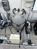
Upon reducing the temp with cold pool water, and going back to hot tub mode the temp prob read correctly. I think the issue is the placement of the sensor since the pool automation installer originally placed it downstream of the heater (incorrect), and subsequently put it upstream of the heater, but on a deadhead with no flow for a future solar heater we have no plans to use.
My question is this, what's the best way to fix this? My logic tells me the sensor needs to measure flowing water temp before the heater. Is it better to remove the pipe assembly between the filter and make it a straight pipe and install the sensor there, or should I look into how to plug the existing hole leaving the existing pipe assembly and install it on the elbow by the heater that says probe, or perhaps the one on the pump side before the filter?
I'd like to have my system read accurate temp so I don't wake up to a lobster boil when wanting to use the hot tub.
Thanks for your time!
A little history, my pool is 3 years old now and has a spa that spills over into the pool if it's not in spa mode. I had automation installed about 6 months after by a local outfit with some issues(below).
I had an erratic temp and changed the probe about 6 months ago, calibrated it through the Jandy app.
Today I set the schedule to turn the hot tub on at 100 degrees at 5AM, woke up and it read 83 and my digital meat temp probe showed 104.5. I cycled the spa off to fill the hot tub with cold pool water to get the temp down to 100 again. I've seen these inconsistent temp readings off and on.
Upon reducing the temp with cold pool water, and going back to hot tub mode the temp prob read correctly. I think the issue is the placement of the sensor since the pool automation installer originally placed it downstream of the heater (incorrect), and subsequently put it upstream of the heater, but on a deadhead with no flow for a future solar heater we have no plans to use.
My question is this, what's the best way to fix this? My logic tells me the sensor needs to measure flowing water temp before the heater. Is it better to remove the pipe assembly between the filter and make it a straight pipe and install the sensor there, or should I look into how to plug the existing hole leaving the existing pipe assembly and install it on the elbow by the heater that says probe, or perhaps the one on the pump side before the filter?
I'd like to have my system read accurate temp so I don't wake up to a lobster boil when wanting to use the hot tub.
Thanks for your time!