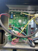
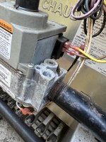
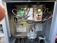
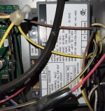
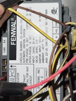
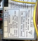
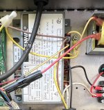
LRZ250EN NG not getting power to the gas valve and I replaced the ignition control with no luck. Any suggestions would be helpful.

Mar 14, 2018
9
Davenport, FL
Pool Size
12000
Surface
Plaster
Chlorine
Salt Water Generator
SWG Type
Pentair Intellichlor IC-40

Attachments

  • 644D1946-7564-4810-8D6B-97FD6EFE82DC.jpeg
    644D1946-7564-4810-8D6B-97FD6EFE82DC.jpeg
    473.2 KB · Views: 12
  • A895EE28-88D1-4031-A303-99BCFE7C11D1.jpeg
    A895EE28-88D1-4031-A303-99BCFE7C11D1.jpeg
    518.5 KB · Views: 11
  • B5F08601-5F29-4BA1-B000-C1BEE0AD6D38.jpeg
    B5F08601-5F29-4BA1-B000-C1BEE0AD6D38.jpeg
    555.1 KB · Views: 12
Can you confirm that the wiring/connection diagram is exactly as shown on the troubleshooting guide that you listed? I have to assume that you are using a multimeter and are both competent and safe in its use. Please note that if the diagram shown is correct, the "B" connection from the power supply to the ignitor ( male {bare} side of the quick connect to the ignitor ) is always hot to ground ( possibly you)! Photo of fenwal ignition module is too close up. Would be helpful if you backed off on the photo to show all info on the label. When you say that you are "stuck" on step 13, do you mean that you are not getting 24V to the gas valve and every other measurement in the troubleshooting up to that point has been correct? How are you measuring the voltage to the gas valve?
 
Can you confirm that the wiring/connection diagram is exactly as shown on the troubleshooting guide that you listed? I have to assume that you are using a multimeter and are both competent and safe in its use. Please note that if the diagram shown is correct, the "B" connection from the power supply to the ignitor ( male {bare} side of the quick connect to the ignitor ) is always hot to ground ( possibly you)! Photo of fenwal ignition module is too close up. Would be helpful if you backed off on the photo to show all info on the label. When you say that you are "stuck" on step 13, do you mean that you are not getting 24V to the gas valve and every other measurement in the troubleshooting up to that point has been correct? How are you measuring the voltage to the gas valve?
Thank you for your response. The diagram is exact and I’m competent and safe with the use of a multimeter. That’s correct, I’m not getting 24v to the gas valve when the igniter heats up and every other measurement is correct up until that point. After the igniter heats up there is a click in the ignition module and the voltage flashes up (never makes it to 24v) for a split second and then back to zeros
 

Attachments

  • D5B00397-618F-42D5-A690-DFFE56A7F626.jpeg
    D5B00397-618F-42D5-A690-DFFE56A7F626.jpeg
    586.8 KB · Views: 10
Can you confirm that the wiring/connection diagram is exactly as shown on the troubleshooting guide that you listed? I have to assume that you are using a multimeter and are both competent and safe in its use. Please note that if the diagram shown is correct, the "B" connection from the power supply to the ignitor ( male {bare} side of the quick connect to the ignitor ) is always hot to ground ( possibly you)! Photo of fenwal ignition module is too close up. Would be helpful if you backed off on the photo to show all info on the label. When you say that you are "stuck" on step 13, do you mean that you are not getting 24V to the gas valve and every other measurement in the troubleshooting up to that point has been correct? How are you measuring the voltage to the gas valve?
Here’s a better pic. I should also mention that it worked fine for the last 2 years but hadn’t been used for about 2 months.
 

Attachments

  • 29D122F9-7BA5-429B-B05E-901854E0E9F6.jpeg
    29D122F9-7BA5-429B-B05E-901854E0E9F6.jpeg
    608 KB · Views: 4
Here’s a better pic. I should also mention that it worked fine for the last 2 years but hadn’t been used for about 2 months.
Please move the wiring out of the way so all the data on the label is readable as well as showing the wire connections to the Fenwal.
 
Please move the wiring out of the way so all the data on the label is readable as well as showing the wire connections to the Fenwal.
 

Attachments

  • 6E230985-7B9B-4101-BE78-39A7B56E2102.jpeg
    6E230985-7B9B-4101-BE78-39A7B56E2102.jpeg
    440.6 KB · Views: 4
  • 093D4523-32C7-4F22-B340-35B0BD365409.jpeg
    093D4523-32C7-4F22-B340-35B0BD365409.jpeg
    494.4 KB · Views: 4
  • FD2DF6FE-7526-4E9C-B221-C8B3E6289AD4.jpeg
    FD2DF6FE-7526-4E9C-B221-C8B3E6289AD4.jpeg
    332 KB · Views: 4
I would disconnect the 2 wires at the gas valve and measure the voltage at the wires with the valve disconnected to see if the voltage drops without the gas valve load. Also a full photo of the gas valve tag information would also be useful. Just wondering if the gas valve is a Honeywell VR8105H/VR8205H and what other info is on the tag.
 
I would disconnect the 2 wires at the gas valve and measure the voltage at the wires with the valve disconnected to see if the voltage drops without the gas valve load. Also a full photo of the gas valve tag information would also be useful. Just wondering if the gas valve is a Honeywell VR8105H/VR8205H and what other info is on the tag.
No voltage when disconnected from the gas valve (same as when connected)
 

Attachments

  • BC8EA175-2964-4DAF-9766-CFC6EC2E6D44.jpeg
    BC8EA175-2964-4DAF-9766-CFC6EC2E6D44.jpeg
    525.1 KB · Views: 2

Enjoying this content?

Support TFP with a donation.

Give Support
I thought that you stated that the gas valve voltage climbed very briefly before going to 0 volts? If the fusible link is open, you may have larger problems with the heater. From the full front photo of the heater, I see what seems to be a rusted though hole on the right side of the burner box outside framing and excessive corrosion on the gas valve piping and gas valve. This may be indicative of flue gas spillage out the front of the burner box from a heat exchanger blockage or sooting. This would also open the fusible link as a safety. Just replacing the fusible link is not the solution as the problem that caused the fusible link to open needs to be addressed.
 
I thought that you stated that the gas valve voltage climbed very briefly before going to 0 volts? If the fusible link is open, you may have larger problems with the heater. From the full front photo of the heater, I see what seems to be a rusted though hole on the right side of the burner box outside framing and excessive corrosion on the gas valve piping and gas valve. This may be indicative of flue gas spillage out the front of the burner box from a heat exchanger blockage or sooting. This would also open the fusible link as a safety. Just replacing the fusible link is not the solution as the problem that caused the fusible link to open needs to be addressed.
Yes, it climbed for a split second when disconnected, exactly the same way as it did when it was connected. Definitely not a hole on the right side of the box, that's just paint. No issues with the front of the unit when it comes to heat, I bypassed the top fusible link to test and it fired up so replacing the link Thurs and then run the tests again
 
The voltage is usually nominal at the gas valve. It sounds like the gas valve opens but doesn’t register flame sensor in time and is shut down. If you have compressed air you can clean out the gas jet heads and burner tray. Anytime the fusible link fails, it’s always a cause of concern. Meaning there is a good chance at one point the flames triggered it by coming out the front. It’s probably a good idea to break down the heater and clean the exchanger and everything thoroughly. You may need to verify gas pressure with a manometer if that doesn’t work.
 
The voltage is usually nominal at the gas valve. It sounds like the gas valve opens but doesn’t register flame sensor in time and is shut down. If you have compressed air you can clean out the gas jet heads and burner tray. Anytime the fusible link fails, it’s always a cause of concern. Meaning there is a good chance at one point the flames triggered it by coming out the front. It’s probably a good idea to break down the heater and clean the exchanger and everything thoroughly. You may need to verify gas pressure with a manometer if that doesn’t work.
Breaking down the heater and cleaning everything was the key! Found mice had gotten to fusible link wire and remote wiring but oddly enough the the wiring was still touching so got the proper voltage when checked. Fixed the wiring and fired right up. Thank you.
 
  • Like
Reactions: Poolbreh
Thread Status
Hello , This thread has been inactive for over 60 days. New postings here are unlikely to be seen or responded to by other members. For better visibility, consider Starting A New Thread.