Jandy 2 Speed Pump Wiring

tonygret

Active member
Sep 18, 2022
42
Vero Beach, FL
Pool Size
8200
Surface
Plaster
Chlorine
Salt Water Generator
SWG Type
Hayward Aqua Rite (T-15)
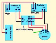
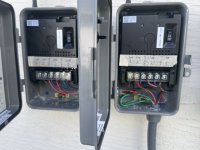
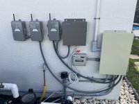
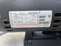
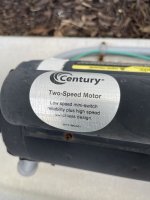
I have the Jandy two speed pump listed in my signature. I want to take it off the two analog Intermatic timers and put it in two 240v wifi timers. Both WiFi timers are DPDT and are rated at 40amps, 240V. My question is how do I wire the new timers to the pump. I can’t seem to find a diagram for my pump, and I am making all the connections in the sub panel. I did all the preliminary wiring to the panel and mimicked the timer wiring (I believe) . See the image below.

Any help would be appreciated.
 

Attachments

  • D9EC54EB-84A2-400C-88D3-740CBA53FAA4.jpeg
    D9EC54EB-84A2-400C-88D3-740CBA53FAA4.jpeg
    265.5 KB · Views: 13
  • 8E2F4C40-C660-4D8A-A1F2-6F2B3B76EA0E.jpeg
    8E2F4C40-C660-4D8A-A1F2-6F2B3B76EA0E.jpeg
    466.6 KB · Views: 10
Tony,

To run a 2-speed pump you should be using a SPDT relay. This is needed to prevent the High speed and Low Speed from ever accidently coming on at the same time.

Maybe just me, but I can't tell anything based on the quality of the images. :(

Let's see what our other members have to say.

Thanks,

Jim R.
 
Is the pump wired for 240V or 120V?

Post a pic of your motor data plate which shows how the motor needs to be wired.

Post a link to the manual for your WiFi timer.

Post pics of the two analog Intermatic timers wiring.
 
So after playing with a DVOM I realized that one leg is common, one is high and one is low and 240v. But with two DPDT switches, it would be possible for both legs to be hot at the same time. Obviously, not ideal. Is there a relay that could fix this, and if so, can you steer me in the right directions.
 

Attachments

  • 8D7D7FCE-3D03-4D2D-B32C-4FF2DA8F2455.jpeg
    8D7D7FCE-3D03-4D2D-B32C-4FF2DA8F2455.jpeg
    319.9 KB · Views: 6
  • ABC4B082-A4A2-440E-A4D2-076C62DC9491.jpeg
    ABC4B082-A4A2-440E-A4D2-076C62DC9491.jpeg
    269 KB · Views: 6
You use one switch to turn pump on and off.

You use other switch to switch between LOW and HIGH speed.

1669581167502.png

Switch1:
  • CB 240V power to LINE1 & LINE2
  • LOAD1 to pump Common
  • LOAD2 to Switch2 LINE
Switch2 must be a SPDT switch:
  • LINE from LOAD2 of Switch1
  • LOADA to HIGH SPEED screw on pump
  • LOADB to LOW SPEED screw on pump
Switch2 toggles LINE between LOADA or LOADB. Never both at same time.
 
Unfortunately, both switches are DPDT and they don’t make a toggle switch in this brand. Keep in mind I am still using the analog timers and the new switches are not connected to anything. The sad part is since I already punched out the connectors on the timers they are not returnable, not to mention the cost of the wire.

In my mind it was a simple as using one pair of wires for high and the other for low, and I never considered that it was possible for both to mistakenly be in at the same time.

I am wondering since I am already this invested, is there a relay or switch that will kill power to one of the legs when the other is on.
 
I found this 240v NC relay here, that will kill the power to the low side when I switch on the high side. My worry is that there may be a sight delay when the relay breaks the low side power, possibly a tenth of a second where both the low and high side is hot on the motor. My question is, can both the high and low sides be hot for a split second, or is that the end of the motor?
 
I found this 240v NC relay here, that will kill the power to the low side when I switch on the high side. My worry is that there may be a sight delay when the relay breaks the low side power, possibly a tenth of a second where both the low and high side is hot on the motor. My question is, can both the high and low sides be hot for a split second, or is that the end of the motor?

I think you risk damaging the motor. You want a SPDT relay that breaks one circuit before it makes the other.
 
How about this one? The motor draws 6.4 amps at high speed, so this should handle the load.

SPTD Realy - https://amzn.to/3F8Htwr

That should work. You use switch2 to turn power on or off the relay coil and switch LINE2 of the pump between the HIGH and LOW speed connections.
 

Enjoying this content?

Support TFP with a donation.

Give Support
Yes, that's how I will wire it. I have the relay and some connectors on the way. When they are all here and installed, I will follow up with you and let you know if I got it working or if I electrocuted myself. :oops:
 
  • Wow
Reactions: JamesW
Can anyone tell me if this wiring diagram makes sense? I just received the relay shown in the image.
 

Attachments

  • Realy.JPG
    Realy.JPG
    34.1 KB · Views: 8
  • Pool Relay Wiring Diagram.jpg
    Pool Relay Wiring Diagram.jpg
    67.4 KB · Views: 8
It worked! It seems no one is reading this post any longer. But for the next guy looking to add a zwave or WiFi timer to their 2 speed pump, this project was a success. Please use the diagram and the relay sown in my previous post for a 2 speed, 240v pump. It’s similar for a 120v two speed pump but the diagram would not work without tweaking.

I can now make all the adjustments to the timers from my phone and collect power usage stats. It also works with Alexa. “Alexa, set the pool pump to high speed”, etc.

Anyway, thanks for all who responded.
 
  • Like
Reactions: JamesW
Thread Status
Hello , This thread has been inactive for over 60 days. New postings here are unlikely to be seen or responded to by other members. For better visibility, consider Starting A New Thread.