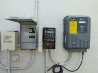
Hello I have a similar question. Just bought house with pool. Have a pentair variable speed 240v pump, and truclear jandy clorinator setup for 240v. Pump is on circuit 1 and clorinator is on circuit 3. Circuit 2 is led light. I'm not getting 240 on circuit 3 it seems and confused on what to do. See pics. How can I get clorinator to power up.

Electrical help for jandy truclear
- Thread starter Mbarrera77
- Start date
You are using an out of date browser. It may not display this or other websites correctly.
You should upgrade or use an alternative browser.
You should upgrade or use an alternative browser.
flynwill
Well-known member
It is indeed "confused".
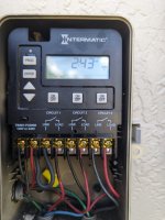
It looks like the two wires coming from the Truclear are simply wired across the circuit 3 contact as though there were a separate source of power going to the tru-clear box.
I would open up the Truclear and check the wiring there.
I would have expected Terminal 7 to be jumpered to terrminal 3, and the black wire currently on terminal 7 would be spliced to one of the wires on terminal 1. (Those terminals can only take 2 wires so you will need to add a splice and a short jumper.)
Also be aware there is some danger when 240 loads are switched in this way. The equipment is still "Hot" even when off (because only one leg of 240 had been shut off). Be very sure to turn off the breaker when working on the pump or TruClear.

flynwill
Well-known member
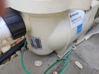
Also I see a capped off blue wire from the conduit coming from the pump. Is it possible you have a two speed pump and it's been effectively wired to a single speed?
- Jul 21, 2013
- 65,062
- Pool Size
- 35000
- Surface
- Plaster
- Chlorine
- Salt Water Generator
- SWG Type
- Pentair Intellichlor IC-60
Why is the chlorinator on its own timer circuit?
Wire the chlorinator to the same connections as the pump and be switched on and off with the pump.
Who did the wiring for that timer?
Wire the chlorinator to the same connections as the pump and be switched on and off with the pump.
Who did the wiring for that timer?
flynwill
Well-known member
I would bet the timer was originally setup for a two-speed pump, in which case using the third contact to enable the chlorinator for either of the two speeds would be a sensible setup (That timer has a mode where circuits 1 and 2 are for a 2-speed pump and the third can be for a cleaner/booster pump, but is just as applicable for a chlorinator). I would speculate that the pump was replaced with the the VS pump which would explain the capped off wire, and whoever did that (probably the previous owner) didn't know what they were doing (but did manage to get the light on the now free extra circuit of the timer).
In any case if it were mine i would probably rewire to use the timer mode where circuits 1 & 2 are both for the pump (switching both legs), wire the pump and chlorinator in parallel and move the light to circuit 3.
In any case if it were mine i would probably rewire to use the timer mode where circuits 1 & 2 are both for the pump (switching both legs), wire the pump and chlorinator in parallel and move the light to circuit 3.
So spoke to the old owner and yes he stated the pump was replaced from a two-speed Jandy to the Pentair which manages its own variable speeds on the pump itself. So basically eliminated the two-speed circuit on the timer. The blue-capped cable is not needed and is capped at both the timer and pump motor. I am not sure why the chlorinator is on its own circuit, to be honest, but it's definitely not receiving the power needed to turn on.
So is the consensus to rewire all?
Run the chlorinator on the same circuit 1 as pump?
Or is it possible to make the tru clear run on 120v?
Sorry not an electrician, but good at doing what's needed by pros like you.
So is the consensus to rewire all?
Run the chlorinator on the same circuit 1 as pump?
Or is it possible to make the tru clear run on 120v?
Sorry not an electrician, but good at doing what's needed by pros like you.
- Jul 21, 2013
- 65,062
- Pool Size
- 35000
- Surface
- Plaster
- Chlorine
- Salt Water Generator
- SWG Type
- Pentair Intellichlor IC-60
Or is it possible to make the tru clear run on 120v?
See page 14 https://www.jandy.com/-/media/zodia...3500.pdf?rev=7f05ef570d984994831ef618a6cf6529
Input Voltages: 120/240 VAC

flynwill
Well-known member
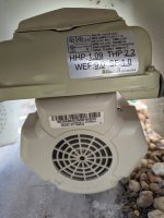
Can you post the model number for the VS pump? Many have their own timer an are meant to be continuously powered. and a few have an aux relay that can be used for a SWG. If that is the case ignore the rest of this post for the moment.
You could switch the SWG to 120 V but there would be not benefit in doing so. I would recommend that you open the cover on the SWG box and confirm the wiring is 240V against the drawing in the manual. Also check that there are no other wires besides the Red, Black and Green we can see coming from the timer.

Also check your timer model I think you have this one:
https://dtrermj9469s.cloudfront.net/userfiles/images/inriver/original/42502_p1353me instructions.pdf
Assuming this is all correct and we want to continue to use the Intermatic to control the pump schedule:
For the fix you're going to need a short (maybe 5-6") bit of 12 Gauge black wire and a wire-nut suitable for 3 #12 wires. There are two options, the "minimal way" or the "best way".
Minimal way:
Turn off both the pump circuit breaker and the lights circuit breaker, and if you have tester available verify that the connections on the timer are dead.
Remove the black wire going to the pump from terminal 1
Connect one end of your bit of black wire to terminal 1 (where the wire to the pump was)
Remove the black wire going to the SWG from Terminal 7
Use the wire nut to connect the three black wires together (Terminal 1, Black to pump, Black to SWG).
Remove the Red wire going to the SWG from Terminal 8 and connect it to Terminal 4 (in addition to the red wire going to the pump).
Turn the breaker breakers back on, and now the SWG should come on when the pump does.
Best way:
We will re-program the timer to use it's "Mode 5" this will dedicate circuits 1 and 2 to work together to switch both legs to the pump and SWG and Circuit 3 will become the timer circuit for the lights:

Turn off the pump and ligjht circuit breakers, and if you have tester available verify that the connections on the timer are dead.
Remove the Black and Red wires going to the SWG from terminals 7 & 8.
Disconnect the red wire from terminal 6 (light switched leg) and connect it to terminal 8.
Disconnect the black wire from terminal 5 (light power) and connect to terminal 7.
Disconnect the black wire going to the pump from terminal 1.
Connect a short 12 gauge black wire from Terminal 1 to Terminal 5.
Connect the black wires for both the pump and the SWG to Terminal 6
Connect the red wire for the SWG to terminal 4 (where the red wire for the pump is connected).
Turn the breakers back on and following the directions in the timer manual set the timer to "Mode 5".
You could switch the SWG to 120 V but there would be not benefit in doing so. I would recommend that you open the cover on the SWG box and confirm the wiring is 240V against the drawing in the manual. Also check that there are no other wires besides the Red, Black and Green we can see coming from the timer.
Also check your timer model I think you have this one:
https://dtrermj9469s.cloudfront.net/userfiles/images/inriver/original/42502_p1353me instructions.pdf
Assuming this is all correct and we want to continue to use the Intermatic to control the pump schedule:
For the fix you're going to need a short (maybe 5-6") bit of 12 Gauge black wire and a wire-nut suitable for 3 #12 wires. There are two options, the "minimal way" or the "best way".
Minimal way:
Turn off both the pump circuit breaker and the lights circuit breaker, and if you have tester available verify that the connections on the timer are dead.
Remove the black wire going to the pump from terminal 1
Connect one end of your bit of black wire to terminal 1 (where the wire to the pump was)
Remove the black wire going to the SWG from Terminal 7
Use the wire nut to connect the three black wires together (Terminal 1, Black to pump, Black to SWG).
Remove the Red wire going to the SWG from Terminal 8 and connect it to Terminal 4 (in addition to the red wire going to the pump).
Turn the breaker breakers back on, and now the SWG should come on when the pump does.
Best way:
We will re-program the timer to use it's "Mode 5" this will dedicate circuits 1 and 2 to work together to switch both legs to the pump and SWG and Circuit 3 will become the timer circuit for the lights:
Turn off the pump and ligjht circuit breakers, and if you have tester available verify that the connections on the timer are dead.
Remove the Black and Red wires going to the SWG from terminals 7 & 8.
Disconnect the red wire from terminal 6 (light switched leg) and connect it to terminal 8.
Disconnect the black wire from terminal 5 (light power) and connect to terminal 7.
Disconnect the black wire going to the pump from terminal 1.
Connect a short 12 gauge black wire from Terminal 1 to Terminal 5.
Connect the black wires for both the pump and the SWG to Terminal 6
Connect the red wire for the SWG to terminal 4 (where the red wire for the pump is connected).
Turn the breakers back on and following the directions in the timer manual set the timer to "Mode 5".
Last edited:
flynwill
Well-known member
Also, given what the previous owner stated and what we are finding it is reasonable to conclude that the SWG has not been operational since the pump replacement, which makes me wonder if the SWG is functional.
Here are the Pumps information/Serials. Owner says SWG was working but prior to me moving in changed the pump out and rewired things so that is possibly the issue. He showed me a picture a few months back of it working.
Attachments
flynwill
Ok so to be clear on the Best Way which i like better:
Terminal 1 - Black Power from 240 Breaker and Jumper to Terminal 5
Terminal 2 - Red Power from 240 Breaker
Terminal 3 - Empty
Terminal 4 - Red from SWG
Terminal 5 - Jumper from Terminal 1 to Terminal 5
Terminal 6 - Black Pump and SWG Black Cables
Terminal 7 - Black Pool LIght
Terminal 8 - Red Pool Light
Can I ask an obvious question (not being an expert) why is there two connected black wires for both the pump and the SWG to Terminal 6 (when there used to be a red there instead) that's the only one that I'm scratching my head to understand
flynwill
Well-known member
Ah, indeed. As I suspected that pump does has it's own timer and is meant to be continuously powered so that it's own clock can keep time. So ideally that is what you would do. But then the problem is how to control the SWG. I don't know what the implications are when running a VS pump like this from an external timer, perhaps others can comment.
The primary concern is that the SWG not be able to receive power if the pump is not running. The SWG should have a flow-switch as a safety measure, but you do not want to depend on that as the sole means of shutting off the SWG when the pump it not running.
There are some folks here on this board who just use a conventional time (like your Intermatic) and program it to the same time period as the pump program. But care has to be taken to be sure the two timers remain in sync.
There are others who have used a "current relay" to sense when the pump is running and use that to control the SWG. IMHO that would be the best solution, but it is not a trivial project see this thread:
Current Sensing Relay for SWG with Variable Speed pump
As in addition to the relay you will need a suitable NEMA enclosure, and some electrical know how.
flynwill
Well-known member
Some corrections:
Terminal 1 - Black Power from 240 Breaker and Jumper to Terminal 5
Terminal 2 - Red Power from 240 Breaker and leave existing jumper to terminal 3
Terminal 3 - Jumper from terminal 2
Terminal 4 - Red from SWG and red from Pump
Terminal 5 - Jumper from Terminal 1 to Terminal 5
Terminal 6 - Black Pump and SWG Black Cables
Terminal 7 - Black from Pool LIght breaker
Terminal 8 - Red Pool Light
The Red wires from the pump and SWG both connect to the load side of Circuit 1, which switches them to the red wire from the breaker (via that jumper to terminal 2). The Black wires from the pump and SWG both connect to the load side of Circuit 2, which switches them to the to the black wire from the breaker (via the jumper to terminal 1).
Terminal 1 - Black Power from 240 Breaker and Jumper to Terminal 5
Terminal 2 - Red Power from 240 Breaker and leave existing jumper to terminal 3
Terminal 3 - Jumper from terminal 2
Terminal 4 - Red from SWG and red from Pump
Terminal 5 - Jumper from Terminal 1 to Terminal 5
Terminal 6 - Black Pump and SWG Black Cables
Terminal 7 - Black from Pool LIght breaker
Terminal 8 - Red Pool Light
Hopefully with my correction it will make sense. Note that there are two black wires coming from the breaker box to the timer, one for the light and one for the pump. It is very important to not mix these up. (The conduit is short enough that you can probably just wiggle one and confirm which breaker it goes to inside the breaker panel.)Can I ask an obvious question (not being an expert) why is there two connected black wires for both the pump and the SWG to Terminal 6 (when there used to be a red there instead) that's the only one that I'm scratching my head to understand
The Red wires from the pump and SWG both connect to the load side of Circuit 1, which switches them to the red wire from the breaker (via that jumper to terminal 2). The Black wires from the pump and SWG both connect to the load side of Circuit 2, which switches them to the to the black wire from the breaker (via the jumper to terminal 1).
flynwill
Well-known member
If you want to have the Intermatic just run the SWG and use the pump's timer for controlling the pump (and carefully keeping the two schedules in sync). The connections would be:
Terminal 1 - Black Power from 240 Breaker and Jumper to Terminal 5
Terminal 2 - Red Power from 240 Breaker and leave existing jumper to terminal 3
Terminal 3 - Jumper from terminal 2 and Red to pump
Terminal 4 - Red from SWG
Terminal 5 - Jumper from Terminal 1 to Terminal 5 and Black to pump
Terminal 6 - Black to SWG
Terminal 7 - Black from Pool LIght breaker
Terminal 8 - Red Pool Light
SWG is powered up and operational. Thank you all for your help and clarity. Much appreciated.
flynwill
Well-known member
Thread Status
Hello , This thread has been inactive for over 60 days. New postings here are unlikely to be seen or responded to by other members. For better visibility, consider Starting A New Thread.