Manual Fill Line Motorized Ball Valve

aaronc1976

Active member
Jun 10, 2021
43
Simi Valley/CA
I want to thank this forum in advance for the help that I undoubtedly know I will receive. I have gotten tons of incredibly useful advice from this forum that has helped get to the point where I finally used my pool for the first time yesterday!

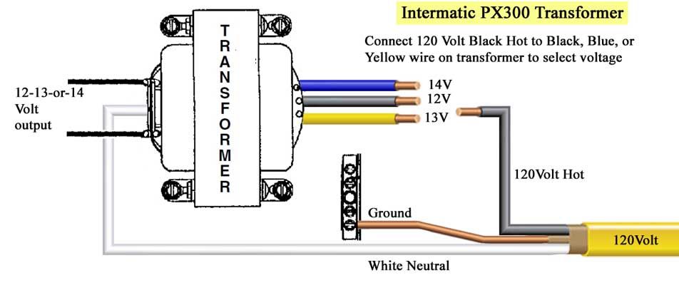
Let me explain what I am trying to do. I have a motorized ball valve that controls a 1/2" fill line that runs to the pool. The valve takes 12 VDC power. I also have a fire pit with electronic ignition and both are sharing same breaker, different relays. Long story short fire pit works, fill line doesn't. I have a 15 amp breaker that I wired to Aux 4 and jumped power from Aux 4 to Aux 5. Aux 4 load runs to fire pit and Aux 5 over to an Intermatic PX50 transformer. Wiring diagram showed yellow on the low voltage side as 12V and red as common. I purchased a 12 VAC to 12 VDC converter/rectifier which has brown and blue wires exposed on each end. I connected the yellow 12 VAC from transformer to brown on converter and blue to red on the AC side. Ball valve has red and black for positive/negative. On DC side of converter, I connected red to brown and black to blue. Fire pit fires up without issue when hitting the Aux 4 button but I can't seem to get ball valve to turn on when hitting Aux 5 button. I confirmed all relays are plugged in on low voltage side of Easytouch 8. Attached are pics of the converter and the relays where I jumped power.
 

Attachments

  • PXL_20220223_003734427.jpg
    PXL_20220223_003734427.jpg
    320.4 KB · Views: 19
  • PXL_20220223_004022283.jpg
    PXL_20220223_004022283.jpg
    465.2 KB · Views: 19
Do you have a multimeter?

Have you measured the voltage on the AUX5 load screws?

You should be able to diagnose where your problem is measuring the voltage at various points.
 
You need one for a project like you are doing.


I can’t follow words. I need to see it and follow the picture.
Ok, so I tested and there is 120 V on terminal 1 but nothing on the load terminal when I activate the Aux 5 . Bad connection at the terminal possibly or do you think installers mixed up when plugging in the relays on the low voltage side? What should I check next?
 
Check that the relay is plugged into AUX5.

Use the continuity function of the multimeter any see if there is continuity between line and load screws when the relay should be ON.
 
Aaron.

All the Intermatic transformers I have seen have the colored wires on the Primary (Input) side of the transformer and two black wires on the Secondary (Output) side of the Transformer.. Backwards to normal transformer operation.

I think your transformer is installed backwards. It this is true, then I doubt it is any good any more or maybe it has a fuse.


Thanks,

Jim R.
Attached is wiring diagram on inside of enclosure. I'm not seeing what you are saying. It is showing normal high voltage in, low voltage out.
 

Attachments

  • PXL_20220223_050735922.jpg
    PXL_20220223_050735922.jpg
    412.6 KB · Views: 5
Check that the relay is plugged into AUX5.

Use the continuity function of the multimeter any see if there is continuity between line and load screws when the relay should be ON.
Here is a picture of multimeter. Do you mind teaching me how to do a continuity test between line and load on Aux 5? I'm really sorry to ask. I had one before but never used it. I somehow dropped it a while ago and it doesn't turn on. This one I just picked up from Harbor Freight. Do I choose the diode symbol?
 

Attachments

  • PXL_20220223_045556726.jpg
    PXL_20220223_045556726.jpg
    486.2 KB · Views: 2
Use the Ohm resistance setting. One click to the left of the diode on the 200.

Note what the display shows without the probes touching. That is an open circuit.

Touch the probes together and it should display 0 indicating a closed circuit.

Now go test the relay. Disconnect wires from the LINE screws before testing.
 

Enjoying this content?

Support TFP with a donation.

Give Support
Check that the relay is plugged into AUX5.

Use the continuity function of the multimeter any see if there is continuity between line and load screws when the relay should be ON.
One other thing I am thinking of. I think I may have screwed up. See if you can follow. I have line from transformer and line from fire pit come into a junction box. Ground wires are nutted together and brought into the sub panel to the ground bus bar. But, I brought two separate neutral wires for each line from junction box into the sub panel and put the 2 neutral wires on the neutral bus bar in the panel in two separate slots. Hot wire for each line was brought into panel to load terminals for Aux 4 and Aux 5. Should I have nutted all neutrals together in junction box and only brought one into the panel's neutral bus bar? I'm wondering if I effectively broke the circuit since this is all on one circuit and if that would explain power to line terminal but not load?
 
People who describe electrical circuits with words often describe what they thought they did and it may be different from what they actually did.

Either draw a wiring diagram or preferably post pics that allow us to follow the entire circuit.
 
People who describe electrical circuits with words often describe what they thought they did and it may be different from what they actually did.

Either draw a wiring diagram or preferably post pics that allow us to follow the entire circuit.
Ok, so I tied all neutrals together and removed extra neutral wire from neutral bus bar. I'm still not getting any voltage. I'm attaching pics of panel, the relay plugs, the junction box and the transformer enclosure. To run resistance test, I set to 200 Ohms just to the left of the diode symbol like you said and put red lead on load terminal screw and black lead on ground bus bar. The display appeared to show it was not an open line. Without touching anything it was a 1 and when I ran the test, the numbers moved. Did I perform the test properly?
 

Attachments

  • PXL_20220223_180104128.jpg
    PXL_20220223_180104128.jpg
    477.4 KB · Views: 6
  • PXL_20220223_180112002.jpg
    PXL_20220223_180112002.jpg
    503.2 KB · Views: 7
  • PXL_20220223_180843534.jpg
    PXL_20220223_180843534.jpg
    470.7 KB · Views: 7
  • PXL_20220223_180555678.jpg
    PXL_20220223_180555678.jpg
    349.5 KB · Views: 7
Nope, all you needed to test was between the LINE screw and the LOAD screw when you turn AUX5 on and off.

I don’t know why you think you need to test to the ground bus bar.

You are not dealing with appliances where your just plug stuff together. You seem to lack an understanding of how to do electrical design and troubleshooting.

You need to start at the beginning of your circuit and follow the electrical path using voltage and continuity until you find your problem. Be careful working with the 120V side.
I apologize for my ignorance and thanks again for all the help you freely provide. Just to be clear, I pull the wires out of both line and load and measure as I click the Aux 5 button or do I leave load line plugged into screw? Again, truly sorry for my stupidity.
 
Disconnect the wires from the screws.

The objective of the test is to confirm the relay works properly and opens and closes the circuit between the LINE and LOAD screws.

You need to test each piece of your puzzle in similar ways to figure out what works and what does not work as you expect. But in order to do that you need to understand how things are supposed to work.

Do you understand how a relay works?

Do you understand what continuity in an electrical circuit is?
Yes I do understand all that just did not know how to do all the testing. Again, sorry for being dumb. At any rate, I ran the test and at first, remained at 1 so for ***** and giggles I tested all unused relays, aux 3, ,5, 6 and 7 also measured at 1. I traced all relay wires to the low voltage side and 3 and 5 were swapped and 6 and 7 were swapped. I removed and plugged into the proper corresponding spots and voila! I guess installers did not trace properly when plugging in the relays. Issue is now fixed! I want to thank you once again for all your excellent help and for politely dealing with my ignorance! You are amazing!!
 
Glad you figured it out. In post #6 I wrote - Check that the relay is plugged into AUX5.
 

Enjoying this content?

Support TFP with a donation.

Give Support
Thread Status
Hello , This thread has been inactive for over 60 days. New postings here are unlikely to be seen or responded to by other members. For better visibility, consider Starting A New Thread.