Jandy JXI 400N Blower not working

jandydandytrouble

New member
Jan 27, 2022
3
Houston, TX
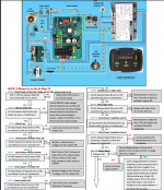
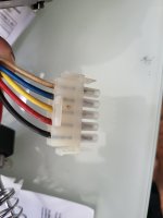
Hello, hoping someone can provide me with some troubleshooting advice. I have a Jandy JXI 400N and the blower isn't coming on any more. I don't think the blower is bad because I have replaced the blower with a new blower and I have the same symptom. I followed the troubleshooting guide and on step 12 for troubleshooting the blower I am a little confused. In particular, the step walks through checks on the power distribution board to the blower. I have checked each wire going to the blower and ground and I see 120V on each wire. However, in the troubleshooting guide on step 12 it says to check voltage between Black (L) to blower PDB and white wire? Which white wire? The white wire going to the blower PDB? The color coding on the wires in their PDB diagram are also different than my blower power connector (attached) I'm trying to determine if I need to replace the power distribution board.

I'm pretty sure my blower isn't powering on but I don't exactly remember how subtle the blower is when it is started. I have put my hand on the blower motor and I notice no change in vibration when I power on the heater. I also don't notice any difference in sound. My assumption is the blower isn't on.
 

Attachments

  • jxi_blower_troubleshooting.png
    jxi_blower_troubleshooting.png
    163.8 KB · Views: 63
  • 20220127_152156.jpg
    20220127_152156.jpg
    179.8 KB · Views: 37
Welcome to TFP.

When the blower runs you will hear it.

You sure all of the safety switches in steps 4 through 9 are all good?

@setsailsoon has been into the guts of his JXI heater and may be of help. Or @swamprat69
 
Is your heater wired for 240 volt or 120 volt power? When you say you have checked the wires to the blower and have 120 volts on each wire do you mean 120 volts measured to ground? If your heater is powered by 240 volts, checking blower wires to ground doesn't mean anything as one leg of 240 volt power through a resistive load will measure 120 volts to ground on both sides of the load. I think that you may have skipped a couple of troubleshooting steps in the sequence of operation as there are several operations that must take place before the blower is powered. It would be helpful to have photos of all of your wiring and electrical components as wiring designations and controls may have changed with different versions of the heater over the years.
 
Is your heater wired for 240 volt or 120 volt power? When you say you have checked the wires to the blower and have 120 volts on each wire do you mean 120 volts measured to ground? If your heater is powered by 240 volts, checking blower wires to ground doesn't mean anything as one leg of 240 volt power through a resistive load will measure 120 volts to ground on both sides of the load. I think that you may have skipped a couple of troubleshooting steps in the sequence of operation as there are several operations that must take place before the blower is powered. It would be helpful to have photos of all of your wiring and electrical components as wiring designations and controls may have changed with different versions of the heater over the years.
Hello, The black and red wires coming into the power distribution board each read 120V and the card is set to 240V. I pulled out the card and noticed that one of the connections on the card almost seemed like it melted and came off when I pulled the card out. After this, I replaced the PDB but this doesn't appear to have solved the issue. I did follow and test all the steps leading up to testing the power on the blower and all the steps were good (steps 3 through 11). The wire coloring on the troubleshooting diagram doesn't appear to match my blowers connector. I have attached some more pictures of the blower motor wiring diagram. I think you are right that the blower isn't being powered but I'm not sure how to complete the last troubleshooting step to test for 240V between black and white as indicated in the troubleshooting guide. I'm sure the PDB is good now and the wiring is correct.
 

Attachments

  • 20220128_143854.jpg
    20220128_143854.jpg
    249.8 KB · Views: 26
  • 20220128_143906.jpg
    20220128_143906.jpg
    264.9 KB · Views: 26
  • 20220128_104909.jpg
    20220128_104909.jpg
    187.1 KB · Views: 27
Measuring the black and red wires individually (to ground??) will not tell you anything meaningful. Measure between the black and red wires to see if you have 240 volts. Next, measure the secondary output from the transformer to see if you have 24 volts. If you have 24 volts output from the transformer secondary, check to see if you have 24 volts between "GND" and "W". If you have 24 volts between "GND" and "W" at the Fenwal ignition control, this should cause the "F1"/"F2" contacts on the ignition control to close and power up the blower.
 
Thread Status
Hello , This thread has been inactive for over 60 days. New postings here are unlikely to be seen or responded to by other members. For better visibility, consider Starting A New Thread.