Section 6. Jandy Valve Actuator6.1
Operation
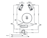
One leg of a 24 VAC transformer secondary supplies voltage to the common terminal of a SPDT (single-pole, double-throw) relay.
The N.C. (normally closed) terminal of that relay is connected to the red wire of the JVA cord, and the N.O. (normally open) terminal is connected to the white wire of the JVA cord.
The completion of the circuit is through the black (common) wire of the JVA cord.
When the coil of the SPDT relay is de-energized, voltage is supplied from one leg of the transformer secondary to the common terminal of the relay and then down the red wire of the JVA cord to the toggle switch at the rear of the JVA.
The toggle switch then routes the voltage to either the lower microswitch (toggle in ON 1 position), the upper microswitch (toggle in ON 2 position), or to neither microswitch (toggle in OFF position).
If the voltage is routed to the lower microswitch, and that microswitch is closed, the voltage passes through the motor to the black wire and then back to the other leg of the transformer secondary to complete the circuit.
The motor will then rotate clockwise, turning the gear train (and ultimately the output shaft) until the lower cam comes in contact with the lower microswitch, which opens the circuit and stops the motor.
If the voltage is routed to the upper microswitch, the motor rotates in the opposite direction until the upper cam lobe comes into contact with the upper microswitch, which stops the rotation.
If the coil of the SPDT relay is energized, the voltage travels through the white wire to the toggle switch, which as above, routes it either to the lower microswitch for clockwise rotation or upper microswitch for counterclockwise rotation, with the voltage traveling back to the black wire to complete the circuit.
The capacitor, which is wired in parallel with the motor, keeps the motor rotating in the correct direction and ensures that the JVA rotates with the proper torque.


