Hi,
I have the Intermatic T103 DPST switch set up and wired from a breaker with power supply as a 4 wire, 3 conductor cable with Black 120vac, Red 120vac, White neutral and copper ground.
I have two 120vac loads to power, one switched, one not on the T103. The first load is a series of outdoor lights around the pool, which is switched. The second load is a series of outlets which is unswitched. I am ok with the dewenwils box controlling both loads as switched together if necessary.
In the Intermatic T103 box is a wiring diagram as attached.

My current setup:
From Breaker: Black to terminal 1, Red to terminal 3, White to terminal A, ground to ground terminal.
Outgoing, the 2 white wires are wirenutted with the white incoming line and again all tied to terminal A. ground to ground, and the switched black line on terminal 2, and unswitched on terminal 4.
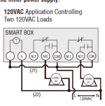
In the WiFi box, wiring diagram link here: http://www.dewenwils.com/d/files/timer/howt01a-instruction.pdf
It doesn't seem to list any diagram for DPST, but I'm hoping there is a way to wire with this box, even if it means that both outgoing lines will operate as one in terms of the timer/switch. I was planning on using the "120VAC Application Controlling Two 120VAC Loads" wiring option, but this doesn't use both black and red "hot" lines coming in from the breaker, but perhaps that's no big deal, and only useful if switching one line was possible, but wasn't sure how using just one would affect the breaker. Just cap off the red line and use the black line in this diagram?
Thanks much for any help!
I have the Intermatic T103 DPST switch set up and wired from a breaker with power supply as a 4 wire, 3 conductor cable with Black 120vac, Red 120vac, White neutral and copper ground.
I have two 120vac loads to power, one switched, one not on the T103. The first load is a series of outdoor lights around the pool, which is switched. The second load is a series of outlets which is unswitched. I am ok with the dewenwils box controlling both loads as switched together if necessary.
In the Intermatic T103 box is a wiring diagram as attached.
My current setup:
From Breaker: Black to terminal 1, Red to terminal 3, White to terminal A, ground to ground terminal.
Outgoing, the 2 white wires are wirenutted with the white incoming line and again all tied to terminal A. ground to ground, and the switched black line on terminal 2, and unswitched on terminal 4.
In the WiFi box, wiring diagram link here: http://www.dewenwils.com/d/files/timer/howt01a-instruction.pdf
It doesn't seem to list any diagram for DPST, but I'm hoping there is a way to wire with this box, even if it means that both outgoing lines will operate as one in terms of the timer/switch. I was planning on using the "120VAC Application Controlling Two 120VAC Loads" wiring option, but this doesn't use both black and red "hot" lines coming in from the breaker, but perhaps that's no big deal, and only useful if switching one line was possible, but wasn't sure how using just one would affect the breaker. Just cap off the red line and use the black line in this diagram?
Thanks much for any help!