
Possible New Pool In Central FL
- Thread starter Tegguy
- Start date
You are using an out of date browser. It may not display this or other websites correctly.
You should upgrade or use an alternative browser.
You should upgrade or use an alternative browser.
- Oct 27, 2019
- 394
- Pool Size
- 17000
- Surface
- Plaster
- Chlorine
- Salt Water Generator
- SWG Type
- Pentair Intellichlor IC-40
Guy,
Neither your System nor your IChlor need a GFCI breaker...
Thanks,
Jim R.
Thank you. Do the lights need GFCI since they are low voltage?
- Oct 27, 2019
- 394
- Pool Size
- 17000
- Surface
- Plaster
- Chlorine
- Salt Water Generator
- SWG Type
- Pentair Intellichlor IC-40
So side question what size breaker should I run for the blower? That data sheet says 9amp current draw so I was thinking a 20amp or possibly 30amp breaker would be good and I could do something like this.
Square D by Schneider Electric HOMT2020220CP Homeline 2-20-Amp Single-Pole 1-20-Amp Two-Pole Quad Circuit Breaker - - Amazon.com
Square D by Schneider Electric HOMT2020220CP Homeline 2-20-Amp Single-Pole 1-20-Amp Two-Pole Quad Circuit Breaker - - Amazon.com
Guy,
You never base a breaker on the load, you only base it on the wire going to the load.. As an example 15 amps for 14 gauge wire and 20 amps for 12 gauge wire etc...
The breaker is there to protect the wiring, not the load.
I don't believe that low voltage lights need a GFCI, but just because they are actually in the water, I would do it anyway.
Jim R.
- Oct 27, 2019
- 394
- Pool Size
- 17000
- Surface
- Plaster
- Chlorine
- Salt Water Generator
- SWG Type
- Pentair Intellichlor IC-40
Guy,
You never base a breaker on the load, you only base it on the wire going to the load.. As an example 15 amps for 14 gauge wire and 20 amps for 12 gauge wire etc...
The breaker is there to protect the wiring, not the load.
I don't believe that low voltage lights need a GFCI, but just because they are actually in the water, I would do it anyway.
Jim R.
Thanks I have 10AWG from the panel but the blower wiring is smaller. Would I be ok with a 30 amp breaker or should I go 15 or 20?
- Jul 21, 2013
- 54,057
- Pool Size
- 35000
- Surface
- Plaster
- Chlorine
- Salt Water Generator
- SWG Type
- Pentair Intellichlor IC-60
You can have a breaker smaller then the amp rating of the wire. The breaker should be sized for the smallest wire on the circuit. The blower installation guide should tell you the appropriate size breaker for it.
- Oct 27, 2019
- 394
- Pool Size
- 17000
- Surface
- Plaster
- Chlorine
- Salt Water Generator
- SWG Type
- Pentair Intellichlor IC-40
You can have a breaker smaller then the amp rating of the wire. The breaker should be sized for the smallest wire on the circuit. The blower installation guide should tell you the appropriate size breaker for it.
Unfortunately this one doesn't. It's an air supply silencer 2HP 220V blower.
- Jul 21, 2013
- 54,057
- Pool Size
- 35000
- Surface
- Plaster
- Chlorine
- Salt Water Generator
- SWG Type
- Pentair Intellichlor IC-60
The manual says it will pull 6 amps @ 240V. You can use a 15 or 20 amp breaker on it if the panel wire is 10 AWG.
- Oct 27, 2019
- 394
- Pool Size
- 17000
- Surface
- Plaster
- Chlorine
- Salt Water Generator
- SWG Type
- Pentair Intellichlor IC-40
@ajw22 @Jimrahbe
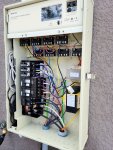
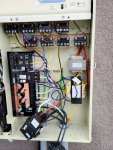
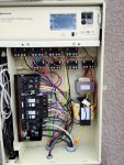
Can either of you help? I installed my new breaker today but noticed some weird wiring. The panel load wire was hooked up to the breaker neutral line and the neutral wire was on the load line on the breaker. When I installed the new breaker I moved the load wire to the neutral bar but I'm thinking this was installed backwards originally.
Similarly on the salt cell the wires were swapped on the breaker. I did move the blue/white wire to the neutral bar in this case. (This also runs up to the relay at top)
I did wire in the new blower motor as well can you comment on if this is hooked up correctly to the relay?
This 1st picture is before I swapped everything with the 2nd and 3rd being my work.
Also am I missing a relay? My door shows there should be 5 on the top row
Attachments
Last edited:
- Jul 21, 2013
- 54,057
- Pool Size
- 35000
- Surface
- Plaster
- Chlorine
- Salt Water Generator
- SWG Type
- Pentair Intellichlor IC-60
Can either of you help? I installed my new breaker today but noticed some weird wiring. The panel load wire was hooked up to the breaker neutral line and the neutral wire was on the load line on the breaker. When I installed the new breaker I moved the load wire to the neutral bar but I'm thinking this was installed backwards originally.
Which breaker are you talking about? You had 3 120V GFCI in the panel.
The top breaker for your IntelliCenter has two black wires from the transformer and it doesn't matter if they connect to the LOAD or NEUTRAL.
Similarly on the salt cell the wires were swapped on the breaker. I did move the blue/white wire to the neutral bar in this case. (This also runs up to the relay at top)
The middle breaker has the violet and white wires from the SWG transformer which form the neutral when using 120V to the neutral breaker connection. The yellow LOAD runs to the relay.
I did wire in the new blower motor as well can you comment on if this is hooked up correctly to the relay?
Your new wiring does look OK to me.
- Oct 27, 2019
- 394
- Pool Size
- 17000
- Surface
- Plaster
- Chlorine
- Salt Water Generator
- SWG Type
- Pentair Intellichlor IC-40
Which breaker are you talking about? You had 3 120V GFCI in the panel.
The top breaker for your IntelliCenter has two black wires from the transformer and it doesn't matter if they connect to the LOAD or NEUTRAL.
Sorry the top breaker used to be the "system" it had the black wire on the bottom breaker port which was labeled as "load neutral" I put this wire on the neutral bar. The violate wire was moved to the top port on the new quad breaker
The middle breaker has the violet and white wires from the SWG transformer which form the neutral when using 120V to the neutral breaker connection. The yellow LOAD runs to the relay.
The yellow wire on the SWG was on the bottom or "load neutral" breaker port I moved this to the bottom port on the quad breaker. The violate/wht wire was on the load power port on the breaker I moved this to the neutral bar.
Your new wiring does look OK to me.
Thank you fingers crossed it works.
Finally fixed all the wiring and got the heater working (love paying people to have to redo their work)
- Jul 21, 2013
- 54,057
- Pool Size
- 35000
- Surface
- Plaster
- Chlorine
- Salt Water Generator
- SWG Type
- Pentair Intellichlor IC-60
If the bottom connection is the LOAD NEUTRAL then your remaining 120V GFCI breaker is wired wrong.
- Oct 27, 2019
- 394
- Pool Size
- 17000
- Surface
- Plaster
- Chlorine
- Salt Water Generator
- SWG Type
- Pentair Intellichlor IC-40
If the bottom connection is the LOAD NEUTRAL then your remaining 120V GFCI breaker is wired wrong.
Given the quality of work I'm not surprised. Ive had to have them out to fix a lot of things.
To be proper I should swap the load and neutral on the system breaker. I might do that one day.
Good news is blower and everything works!
- Jul 21, 2013
- 54,057
- Pool Size
- 35000
- Surface
- Plaster
- Chlorine
- Salt Water Generator
- SWG Type
- Pentair Intellichlor IC-60
Sorry the top breaker used to be the "system" it had the black wire on the bottom breaker port which was labeled as "load neutral" I put this wire on the neutral bar. The violate wire was moved to the top port on the new quad breaker
Violet goes to the neutral bar.
Black goes to the CB LOAD.

- Jul 21, 2013
- 54,057
- Pool Size
- 35000
- Surface
- Plaster
- Chlorine
- Salt Water Generator
- SWG Type
- Pentair Intellichlor IC-60
You should fix the neutrals. Powering the neutrals can create unsafe conditions even though things work.
Guy,
Your 120 volts to the SWCG transformer looks good to me..
Your 120 volts to the System transformer is backwards from my manual. It will work, but it is not correct.. I just think it should be wired per the manual.. My manual says Black is hot and the Violet is Neutral.. You have it wired the opposite way.
Your blower wiring has 240 going to the Aux 4 relay and that looks ok..
IntelliCenters come with 5, 8 or 10 relays.. I assume you have an IC8.. It does not make any difference where you put the relays. It does make a difference where each relay is plugged into the main board.. Obviously it makes sense to have the top left relay as the Pump/Filter relay and then Aux 1, then 2, then 3 etc.. Just keep in mind that some idiot can plug any relay into any spot on the main board.. So just because a relay is physically in the Aux 1 position, does not mean it is plugged into the Aux 1 connection on the main board.
I don't think your original GFCI breakers were mis-wired.. The pigtails from GFCI breakers are wired to the neutral bus, but the neutral connections are not wired to the neutral bus. They go back to the circuit being protected..
Thanks,
Jim R.
- Oct 27, 2019
- 394
- Pool Size
- 17000
- Surface
- Plaster
- Chlorine
- Salt Water Generator
- SWG Type
- Pentair Intellichlor IC-40
Violet goes to the neutral bar.
Black goes to the CB LOAD.
Ok good I'm not crazy cause that's how I read it to I was just confused cause the "professional" had it hooked up different
Turbo1Ton
Gold Supporter
- Dec 26, 2019
- 1,842
- Pool Size
- 14500
- Surface
- Plaster
- Chlorine
- Salt Water Generator
- SWG Type
- Pentair Intellichlor IC-40
Also am I missing a relay? My door shows there should be 5 on the top row
Assuming you have the iC8 Intellicenter? Mine was the same way. For some reason they do not match the layout on the door sticker when they assemble it. I changed mine so that it matched. What's the point of having the sticker with the layout, if the layout is completely wrong??
--Jeff
- Oct 27, 2019
- 394
- Pool Size
- 17000
- Surface
- Plaster
- Chlorine
- Salt Water Generator
- SWG Type
- Pentair Intellichlor IC-40
Assuming you have the iC8 Intellicenter? Mine was the same way. For some reason they do not match the layout on the door sticker when they assemble it. I changed mine so that it matched. What's the point of having the sticker with the layout, if the layout is completely wrong??
--Jeff
Thanks I was confused on this.
Thread Status
Hello , This thread has been inactive for over 60 days. New postings here are unlikely to be seen or responded to by other members. For better visibility, consider Starting A New Thread.