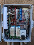
My NEW Pool Automation Controller

Thanks both Kato and Ari...after your responses I thought about it a bit more...and although my forte is NOT AC current I think you two are right. Simultaneous AC current applied to both coils of the motor probably wouldn’t cause any harm (unless possibly left on for long periods...heating?)...and it also would cancel out any “movement” of the spindle due to the lack of phase shifting that normally occurs between those coils, but won’t in this case. I’ll probably still wire as in the diagram and report back if it works.

One thing I know for sure: IF there is a way to hook up those actuators incorrectly and mess it up, I know I WILL do it...it never fails, haha.
 
  • Haha
Reactions: cmc0619
@cmc0619 you talked to kato about hot side of relays (and such) in kato's build thread. I didn't fully follow the conversation. Does this relay setup violate any of your recommendations? Does it look like it will work? I know there is not a terminology that uses +/- sides to describe AC voltage, I just didn't know how else to label it...

I am planning on using this same setup for both of my valves.

View attachment 141272

- side is on the valve. You're switching hot. Looks perfect!
 
  • Like
Reactions: jonpcar
An update…and a near DISASTER…

I completed all the changes to my hardware (moving/adding the relays) last weekend. We have been watching grandkids all week so I haven’t been able to continue except later in the evenings, when I am exhausted…haha.

I have had a problem with my I/O Chip, the MCP23017, a chip which uses the 2-pin I2C bus and gives me an additional 16 programmable input/outputs to drive relays and receive sensor status. I am using 8 of these pins as inputs to monitor relay positions (indicates whether the relays are on/off), and use 7 of the 8 remaining pins as outputs to drive 7 output relays: Stenner Enable, Stenner Chlorine Pump, Stenner Acid Pump, and 4 valve control as described in the preceding posts.

The 8th relay that I drive currently is the Pool LED relay, and I drive that directly from a Photon pin in order to accomplish the relatively fast on/off sequences for LED color control.

Well, the other night, I was experimenting (and uploading the code to my pool controller) and realized I needed to take some voltage readings on the hardware to move forward….too late, so I went to bed. The next morning I went out to my pool pad to take the measurements.

When I opened up my pool controller case… the lights on ALL my control relays were ON (except for the light relay which is controlled by the Photon itself, rather than by the MCP23017). My worst nightmare had come close to fruition: emptying my chemical tanks into the pool.

The ONLY thing that had saved me were those additional connections on my relays that ensured that if BOTH Stenner pumps were turned ON at the same time, then neither would activate. The valves, as we discussed in some previous posts, probably would have been OK, but they didn’t try to turn on either as a result of the relay wiring.

I learned a lesson…my Stenner Pump Enable relay should NOT be controllable by the same “write” operation that controls ON/OFF of the Chlorine/Acid relays. It is obvious now, but I have moved the Stenner Enable output to the Photon, rather than from the MCP23017. My actual problem was not actually a write to the port, it was a reset condition of the MCP23017 that I didn't take into account. The effect was the same: the Stenner Enable and the Stenner ON relays were both accidentally activated at the same time...bad, bad, bad.

I’m still debugging my problem with the MCP23017, so besides the Pool LEDs...I am not yet controlling anything. And I won't even hook up those control relays again until I insure that the MCP23017 is consistently outputting the values I expect.
 
Wow, good lesson learned. You have inspired me to put some more safety checks on my system. Before turning on the SWG or the heater, I will query the pump to read if it is running at least 1500 rpm. If no reply from the pump (ie not running, no power etc) then dont turn on any of that stuff.

I also realized that I need to adjust the priming speed on the pump. When I set my pool to SPA mode and the pump primes at full 3450 rpm the pressure through the system jumps to 45 psi. Dont want that happening again.
 
  • Like
Reactions: jonpcar
Wow, good lesson learned. You have inspired me to put some more safety checks on my system. Before turning on the SWG or the heater, I will query the pump to read if it is running at least 1500 rpm. If no reply from the pump (ie not running, no power etc) then dont turn on any of that stuff.

I also realized that I need to adjust the priming speed on the pump. When I set my pool to SPA mode and the pump primes at full 3450 rpm the pressure through the system jumps to 45 psi. Dont want that happening again.
100% Agree - I realized I don't have enough safety checks in my system either - have you thought about using a flow switch instead of just querying the pump? One of the things I want to do is use a flow switch so I can be smarter about running my pool pump dry (if it didn't prime), turning on the SWG and my yet to be installed Stenner acid pump.
Since I do have a SWG that I already have a flow switch for, I want to avoid having to plumb in a second a flow switch. So I did some research - my flow switch is using a RJ11 connector, but just has two wires. The flow switch is a reed switch that closes when there is flow, the SWG sends 5V to the flow switch, and uses that to detect when it gets 5V back or not..
My idea is to split off the same flow sensor cable - and have it go to both the SWG and to my ESP to allow me to get flow switch data , that I can then use to be smarter about potential problems. I also like your idea Jon of using current sensors to detect when my acid pump is turned on accidentally when it shouldn't be - need to reread your thread to see what part you ordered for that
 
Last edited:
  • Like
Reactions: Katodude
I have a flow switch as well for the SWG, and I have thought of that idea as well. However, I would just use it for the heater and if I added a stenner injection for acid.

I might as well wire up the flow switch and have a status on my controller indicating flow as well. Always fun to add new stuff.
I just thought of a flaw in my plan - the 5V to the flow switch is only sent when the SWG is on.. So for the times I have SWG off, there will be no voltage being sent to the flow switch, so I won't be able to read the flow status. I need to think of a way to read the flow switch when the SWG is off..
 
I think “system checks” are always good...but they are almost always the last thing implemented you get around to it...at least that is what it seems like I am heading toward, haha.
...have you thought about using a flow switch instead of just querying the pump? One of the things I want to do is use a flow switch so I can be smarter about running my pool pump dry (if it didn't prime), turning on the SWG and my yet to be installed Stenner acid pump.
If you have an existing flow switch, it probably is worthwhile to use it to avoid additional plumbing changes. Personally, I don’t appreciate what information a flow switch gives vs a couple other methods. I really, really like my psi gauges and eventually they will be the basis for a lot of -probably useless- information that I will gather and use including flow rate. Also pump wattage provides a lot of information about flow rate if you compare it to known good values (even for priming).

Ari, I haven’t installed my current meter devices yet...that is on hold while I implement more critical items. So I have no data about the success of the parts I ordered...however, they were all cheap parts and will eventually be worth it just to experiment with.

I have a flow switch as well for the SWG, and I have thought of that idea as well. However, I would just use it for the heater and if I added a stenner injection for acid.

I might as well wire up the flow switch and have a status on my controller indicating flow as well. Always fun to add new stuff.
Kato, think about a psi gauge on your filter...that’s a fun project too and could be possibly useful for multiple things. One reason that I like my PSI gauges is that they have been completely reliable over the last year since installation. Absolutely no problems, but that might be because I bought the used “expensive” ones, not sure how the cheaper gauges that I linked to in one of my early posts in this thread would perform.

I just thought of a flaw in my plan - the 5V to the flow switch is only sent when the SWG is on.. So for the times I have SWG off, there will be no voltage being sent to the flow switch, so I won't be able to read the flow status. I need to think of a way to read the flow switch when the SWG is off..
Ari, with a DSPT relay, you can control the on/off of the DSPT’s coil with that flow switch and use the two “poles” (cmc, are you impressed with my terminology? haha) as the switches: one as a replacement for the SWG and the other to any new logic. That would require running some wires around.
 
Last edited:
While I conceptually like the idea of a PSI gauge (really more for the fun of it). I really like having the analogue gauge on the filter. It is a quick check device that has had zero failures in the 10 years I have owned this house and pool. I would be fine supplementing it with another electronic pressure gauge but I dont want to lose the dial.

Now, what I REALLY need is a reliable and accurate pH sensor. I am even willing to splurge a little for this. I would love to be able to pull out the phone check the pH and hit a quick button to dose some acid. With the SWG my FC is steady and rock solid. ph has always been an issue.

I need something that is not a plumbing nightmare (ideally something that I can attach with a 1/2” or 3/4” clamp). If I have to calibrate it once a month or so that is not the end of the world. Would love to hear some great ideas around that.

kato, my proposal for an electronic psi gauge is not necessarily to know psi so that the filter can be backwashed/cleaned...it is an alternative, dynamic check for “pump running correctly” and/or “massive system failure” haha. And you don’t have to lose your gauge:

7DD3A8EC-48D9-41C6-9A5F-9E97D4FF3A29.jpeg

I want to do pH too but that is a bit out in time. Hopefully you can trailblaze through all the problems so that the rest of us can hop on board, ;) . I’m not so worried about plumbing changes required as I have made many of those for various reasons. I want to make sure that the pH reading can be fairly accurate...in particular I am hoping that the recording I do for my chemicals via the Photon and my app, can be used to calibrate the electronic probe pH reading each time I do a manual pH test.

My understanding is that some pH probes allow this 1-point calibration technique although it is not quite as accurate as a method that uses a liquid with a known pH to calibrate (sometimes 2 points).

About insertion of pH without plumbing changes...I have not looked into this yet but I believe that I remember some examples (in my web searches) of people tapping into their pool pump gauge “connections” for at least one side of the water flow. I don’t remember the details
 
Last edited:
  • Like
Reactions: MyAZPool

Enjoying this content?

Support TFP with a donation.

Give Support
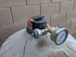
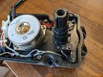
A few posts ago I talked about the modifications to my valve actuators to “monitor” the valve positions. Basically, I stacked some switches on top of the existing switches inside the actuator so that I could verify/monitor the valve positions. Here are the pictures of that effort.

Here is what the original, unmodified Hayward actuator looks like, in particular, look at the single switch on the close side.

62CEF13F-38A6-433B-8A02-F25BD84D3019.jpeg

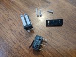
Here is a picture of the key parts of the switch. The “new” parts are the double switch (created by supergluing two new switches together) and the longer screw needed to mount the double switch. Note: you will need 2x this because there are two limit switches inside the actuator that must be replaced.

E67D4E97-9D96-41AB-BA91-4BBBAA77DB51.jpeg

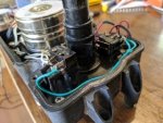
And a picture of the final install, a common ground is shared between the two new switches, and a dedicated wire for each new switch...total of three new wires to run to the pool controller for each valve actuator...I have two.

EAB73A35-99AA-42CF-9078-55E3B5765139.jpeg
 
Another Update

I did (I'm pretty sure) resolve the issue that I was having with my MCP23017 chip. It was a combination of things but I ended up writing my own functions to control the I/O. The library functions were somewhat limiting and I couldn't get the weak pullups on the input pins to work properly...probably a mistake on my part but I don't mind writing code directly for the hardware...that's what I did at Intel for many years.

As a result, I now have my ACID and CHLORINE injections controlled by my controller. I can do manual injections (if I need to as a result of chem testing) and queue them up to occur one after the other. I can also select dosing of those injections over a period of time...say spread out over 8 hours at 15 minute intervals. My user interface does not fully comprehend that capability yet. I can also schedule both of those operations (single injections/dosing operations) via the scheduler.

750E8416-CF35-4AC1-9E89-A5808BE9DFF3.jpeg

So the biggest change is that the acid and chlorine injections now work and they provide proper status for the injection (even if it comes from the scheduler rather than from a manual operation). I still have to add the user interface hooks for chemical "dosing" control...something I plan on experimenting with a bit later in the summer.

Ignore pH and ORP probe slider statuses, those are possibly for the future. I am also still having some problems with my ACID eTape, but I am waiting for that story to resolve to give further updates. Chlorine eTape continues to work. I will be updating the "tracking table sections" for the chlorine and acid tanks soon, but I also have some changes in mind for the user interface there as well, so it might go slowly.

Here is the latest rendition of my hardware. @WannaPool I do have an outlet in my box, but not sure it will stay once I get all my hardware implemented. I kept all my transformers in my "electrical box" and just ran the 24vac over here that I needed for the valve actuators. I've temporarily taken out some of my temperature probes (I still need a stable location for my "ambient" temperature probe...haven't figured it out yet as this area gets full sun in the summer).

I can take out my "motherboard" (that has the Photon) in just a few minutes by disconnecting everything, it only takes a few minutes to get back in as well. Taking out the entire backplane is a bit harder because of the grounding wires and relay outputs but still can be done in about 15 minutes. I had to detach my PVC wire management tube from the backplane and mount it to the side of the case...otherwise I would have had to take out/then re-thread those wires through it every time I wanted to make a change to the backplane, and I still suspect there will be a few. There are a LOT of wires and I really do need to start some labeling.

An additional 8-relay board will stack on top of the relay board that is shown. I still have a number of planned additions to the hardware including current meters (for stenner pumps, pool pump), 220V pool pump powerdown (for reset), aerator valve control (future), pH & ORP (possibly), additional light/landscaping relays. I haven't decided if I am going to electrically isolate the relay boards but would probably add another power supply if I decide to do so.

The "plugged in" phone charger (bottom right) currently supplies the photon (chip at the top middle/left) with voltage via the USB connector. This will probably be removed and I will feed it from the 5V DC DIN power supply. The 24V DC DIN supplies power to drive the relays in my electrical box AND also supplies the voltage source for my PSI gauges (needs from 12-30VDC).

I may mount the antenna (laying horizontally at the top) externally but would probably protect it with some pvc pipe. It does get better reception when it is upright. Finally, the insides of this case get hot (130 Fahrenheit before the summer is really here). I may have to put a fan in this case to vent it.

IMG_20200531_095614.jpg.

NEXT UP: Hooking up the Valve Controls so the pool will go through its cycles automatically rather than manually (IFCS on, skimming, waterfall) as I have been doing since I ripped all that functionality out of my Ecommand4 last week.
 
Last edited:
  • Like
  • Love
Reactions: mguzzy and cmc0619
I want to do pH too but that is a bit out in time. Hopefully you can trailblaze through all the problems so that the rest of us can hop on board, ;) . I’m not so worried about plumbing changes required as I have made many of those for various reasons. I want to make sure that the pH reading can be fairly accurate...in particular I am hoping that the recording I do for my chemicals via the Photon and my app, can be used to calibrate the electronic probe pH reading each time I do a manual pH test.

Well did a bunch of research on pH sensors today as this was really bugging me. They all pretty much need to be calibrated fairly often. Most recommend daily, and the longest they recommend is a week. Not really going to be very helpful since it will take longer to calibrate than to just use a drop test.
 
Well did a bunch of research on pH sensors today as this was really bugging me. They all pretty much need to be calibrated fairly often. Most recommend daily, and the longest they recommend is a week. Not really going to be very helpful since it will take longer to calibrate than to just use a drop test.
kato, I see you started a thread on this topic...good idea, I sure hope there will be someone who already has some good experiences. I’ll respond in more detail there. Did you check out atlas scientific? Their probes list higher recalibration numbers like their lab grade one which lists a year:


Update: My valve control is now up and running. I am running a parallel schedule on my Photon that matches the Ecommand4 pump controller schedule so that valve changes are synced at the right times...remember that my pool pump schedule/RPM is the only thing still controlled by the Ecommand4. The main reason for that is when I am working on new code, I tend to compile and try it out every time I make a change. I don’t want to have to stop/restart the pool pump every time I do that.

But the valve control also lets me make manual changes to the valves (overrides) so that I can run, for example, the waterfall for a given amount of time before it reverts back to the valve schedule.

One question for you Kato (or others) who are controlling valve actuators with two relays: Do you turn off the relay control after your valve has reached its position? I didn’t...but I am thinking about changing that simply because I don’t like the optics of seeing relays activated continuously in my controller. It makes me try to figure out exactly what is going on each time I open it to look at something.

So that was my initial idea as well. I don't like constantly applying power to anything. I turn the power off to my heater when I am done with spa mode. However, this is not the behavior that traditional controllers exhibit. The count on the microswitches. In fact I was even going to time how long to apply power to use that as a way to have an intermediate set point in the valve. Now that I have used Intellivalves I have abandoned that idea. The Intellivalves actually require that they be powered all the time. It still bugs me a little but I am over it.
 
  • Like
Reactions: jonpcar
One question for you Kato (or others) who are controlling valve actuators with two relays: Do you turn off the relay control after your valve has reached its position? I didn’t...but I am thinking about changing that simply because I don’t like the optics of seeing relays activated continuously in my controller. It makes me try to figure out exactly what is going on each time I open it to look at something.

I actually turn off both relays (1 feeding power to my 24VAC transformer and 1 feeding 24VAC to my actuator) once its done switching to it. I don't see any reason to keep either of those items energized 24/7. I have not pulled out my multi meter to see what the actual current draw on idle is, but I figure it prolongs their life to not power it 24/7

Ari
 
  • Like
Reactions: jonpcar
I actually turn off both relays (1 feeding power to my 24VAC transformer and 1 feeding 24VAC to my actuator) once its done switching to it. I don't see any reason to keep either of those items energized 24/7. I have not pulled out my multi meter to see what the actual current draw on idle is, but I figure it prolongs their life to not power it 24/7

Ari

@Katodude and @arib0nd...thanks for the advice on the relays...I made that change and now the valve relays are driven for 20 seconds before shutting off. That gives enough time to rotate the valves to their final position. I don’t turn off the 24vac transformer as Ari does, simply because that transformer is in my electrical box instead of my pool-controller box, but that transformer has been powered 24/7 for about 5 years and would be a cheap replacement.

Unfortunately work on this project has stalled a bit due to full-time care with 3 grandkids (day and night) due to covid hardships. I have cleaned up various sections of code and am expanding my use of the Photon’s 2Kbytes of EEPROM (permanent storage that is not lost at power down).

I previously used 32x8 bytes of this EEPROM for my schedule entries and 16x8 bytes for recent chemical testing entries (pH, FC, cya, TA, CH). I have added one month historical data entries for daily high/low pool temperatures, daily acid injection history, daily chlorine injection history (32 bytes each). All that “historical data” is also permanently stored in the google spreadsheet but it is convenient to have a local copy on the Photon as well. The other main items I will store in this this semi-permanent EEPROM are various parameters that can be modified/compared for pool operation: default values, standard operating parameters such as psi and watts for run-time comparisons to ‘known’ good and/or normal values. These will be used to detect and report “problems” in the system. These values will also be updateable/changeable via the phone app.

But I have an issue with my Ecostar pump. The watts value it is reporting occasionally gets stuck at a previous value and doesn’t change unless I do a power cycle for the pump itself. Prior to a couple months ago, this “stuck watts value” had only happened twice in the previous 5 years. That is one of the reasons that I wanted to dedicate a relay to turn off the power to the Ecostar...if I was traveling, I wanted the ability to reset the pump for this rare occasion. Unfortunately this problem has accelerated in the last couple months and it happens regularly now...every few days. There doesn’t seem to be any other ramifications of this problem except for wrong watts being reported, both over the RS485 bus AND on the pump display.

So, when I have some time, starting next weekend, I will be looking at implementing the AC current monitor for the pool pump to do independent power calculations for the Ecostar. I like having an accurate watts number for a number of reasons which I haven’t talked about much to this point...but i will be using it eventually to fully characterize my systems performance including energy efficiency. I have some ideas for further optimizations of operation of my in-Floor-Cleaning-System (IFCS). I have already spent waaaay too much time on those optimizations, but as I have said before, this has become an enjoyable and educational hobby.

My wife and I have no current plans for further long trips so the urgency for remote monitoring has diminished a bit. I can implement those plans at a slower rate. At this point I think my project implements the minimum requirements I NEED, everything else is gravy, and fun stuff, haha...still so much I can envision including cleanup/expansion of the user interface (Android phone app).
 
Last edited:
I am still doing my final testing on the bench, but I have my updated controller with additional features and safety checks ready to go (for e.g. don't turn on acid and chlorine at the same time.. don't turn on either acid or chlorine if there is no flow... turn off pool pump if its on and there is no flow.. turn off power if pool acid pump is supposed to be off but current is flowing to it). For the last piece, I have a working CT Clamp current sensor - it can measure upto 100 Amps so I am sure it can easily measure your EcoStar wattage.. not sure how its margin of error compares to EcoStars internal reporting.
Also not to hijack your thread... I wanted to show my home-assistant dashboard for the pool. At a high level, I have variables I can set from home-assistant for things like "start time, and durations for my pool pump speeds (high, medium and low), SWG and Acid and also my actuator positions for high, medium and low (to control if I am skimming, vacuuming or both). My NodeMCU device persists these variables locally, so even if home-assistant is offline or the NodeMCU loses connectivity (or power and reboots).. it stores these variables and can run the schedule completely offline. Probably need to make it more user friendly/pretty but seems to work fine on my bench - need to get it installed outside once its not 200 degrees out!


pool-ha.png

@Katodude and @arib0nd...thanks for the advice on the relays...I made that change and now the valve relays are driven for 20 seconds before shutting off. That gives enough time to rotate the valves to their final position. I don’t turn off the 24vac transformer as Ari does, simply because that transformer is in my electrical box instead of my pool-controller box, but that transformer has been powered 24/7 for about 5 years and would be a cheap replacement.

Unfortunately work on this project has stalled a bit due to full-time care with 3 grandkids (day and night) due to covid hardships. I have cleaned up various sections of code and am expanding my use of the Photon’s 2Kbytes of EEPROM (permanent storage that is not lost at power down).

I previously used 32x8 bytes of this EEPROM for my schedule entries and 16x8 bytes for recent chemical testing entries (pH, FC, cya, TA, CH). I have added one month historical data entries for daily high/low pool temperatures, daily acid injection history, daily chlorine injection history (32 bytes each). All that “historical data” is also permanently stored in the google spreadsheet but it is convenient to have a local copy on the Photon as well. The other main items I will store in this this semi-permanent EEPROM are various parameters that can be modified/compared for pool operation: default values, standard operating parameters such as psi and watts for run-time comparisons to ‘known’ good and/or normal values. These will be used to detect and report “problems” in the system. These values will also be updateable/changeable via the phone app.

But I have an issue with my Ecostar pump. The watts value it is reporting occasionally gets stuck at a previous value and doesn’t change unless I do a power cycle for the pump itself. Prior to a couple months ago, this “stuck watts value” had only happened twice in the previous 5 years. That is one of the reasons that I wanted to dedicate a relay to turn off the power to the Ecostar...if I was traveling, I wanted the ability to reset the pump for this rare occasion. Unfortunately this problem has accelerated in the last couple months and it happens regularly now...every few days. There doesn’t seem to be any other ramifications of this problem except for wrong watts being reported, both over the RS485 bus AND on the pump display.

So, when I have some time, starting next weekend, I will be looking at implementing the AC current monitor for the pool pump to do independent power calculations for the Ecostar. I like having an accurate watts number for a number of reasons which I haven’t talked about much to this point...but i will be using it eventually to fully characterize my systems performance including energy efficiency. I have some ideas for further optimizations of operation of my in-Floor-Cleaning-System (IFCS). I have already spent waaaay too much time on those optimizations, but as I have said before, this has become an enjoyable and educational hobby.

My wife and I have no current plans for further long trips so the urgency for remote monitoring has diminished a bit. I can implement those plans at a slower rate. At this point I think my project implements the minimum requirements I NEED, everything else is gravy, and fun stuff, haha...still so much I can envision including cleanup/expansion of the user interface (Android phone app).
 
  • Like
Reactions: jonpcar and cmc0619
Also not to hijack your thread...

ari...don't even worry about it. The more the merrier. I love to see progress like this and you have done it quickly! Congrats!

y NodeMCU device persists these variables locally, so even if home-assistant is offline or the NodeMCU loses connectivity (or power and reboots).. it stores these variables and can run the schedule completely offline.

That was one of my requirements from the start as well...especially with the travels (maybe in the past?) that my wife and I have been doing. I glanced at NodeMCU, it looks similar to my Photon? I thought you were going to go the Raspberry/Node Red route? Or possibly you are using both (a front end and a microcontroller?).

So I’ve looked over your dashboard in more detail and it looks like you have all the building blocks there. Everything looks pretty good. What is that interface built in? Android Studio? Is it available on your phone?
-------------------------

I'm down another "rabbit hole" spending some time over on the OpenEnergyMonitor site. While on the TFP site, I tend to notice comments by posters who consider it an oxymoron to have terms like "calculate" and/or "Raspberry Pi" included in a post that also includes the term "swimming pool"...over on the OpenEnergy site it’s the opposite:

"Are you really trying to measure the current on that toaster oven without a 5Gz Pentium processor?"...haha, I LOVE IT!

No, that's not a quote but I'm having some fun with what I believe will be total overkill for my Pool Controller project. You'll probably end over there looking at their current/power measurement hardware example for your CT Clamp current sensor. Anyway, here's what I''ve been doing in my spare time:

 
Last edited:
13) Update on Milone eTape for Acid/Chlorine Tank Monitoring

Here’s an update on the Milone eTapes which I use to monitor the fluid levels in my Chlorine and Acid tanks. I’ve been waiting to give this update as I was hoping that the eTape for the muriatic acid tank would work out…

In short here is the good news. The Chlorine eTape has performed flawlessly to this point. It has been inserted in (and sometimes out) of my chlorine tank for a total of 8months over the past 13 months. I still worry about it degrading (due to the struggles with the acid eTape), but it hasn’t and my worries are starting to subside.

It is extremely accurate, but so far I have done nothing further with the reading I get from it besides record it, graph it, and use it as a “prediction” (# days countdown) until my chlorine tank is empty…based on the average daily usage for the previous week. Eventually I will use it to monitor the dispersal rate of my stenner pump, to make sure that the dispersal is consistent and not degrading for any reason (tube, etc).

Here’s a graph of my chlorine tank over the last month. You can see that I added chlorine twice. Although it is a 16-gallon capable tank, I’m not filling it to capacity currently because we are home (not travelling) due to Covid…no need.

EDIT: As you will see on the graph, I usually disperse my chlorine once and during the night. I am still planning on some experiments using my "dosing capability" (spreading out the daily dispersal over X number of hours every Y minutes...ex: every 15 minutes). I keep putting that off for other things right now. The plan would be to check that capability during the full sun hours to see how it effects the FC levels during that period. But for now....that's in the future. Anyway, that capability would probably make for a more interesting graph...

Tank Levels (Gallons).png

Now, the bad news…I worked with Milone Technologies to try and get a similar functionality for muriatic acid (MA) tank eTape…. the MA turned out to be too much for “sealing/protection” of the eTape resistance traces. Despite 5 different attempts, the MA started degrading the performance of the eTape within hours. Chris Milone thinks it might be the permeability of the Teflon sleeve itself…or it could still trace to the potting compound used to seal the top of the eTape. He "may" try some additional things to get it to work (different material)…I hope so, because I really do like the chlorine measurement. But at this point, I am moving on.

I am considering a few things that might replace this capability for the Acid Tank, but am wary of the impact that the MA fumes will have on ANY electronics in the vicinity. For now, I will need to use the “estimate method” which will require me to change my user interface to allow entry of MA gallons added to the tank (when I refill). Dispersals will be estimated based on the known Stenner dispersal rate.

I’m disappointed, but only because I really do like that Chlorine eTape.

Besides that, the little time I currently have (still watching grandkids) is being spent sidetracked on the power monitoring aspect of this project…which I am getting way more into than is necessary, but it is a learning experience...
 
Last edited:

Enjoying this content?

Support TFP with a donation.

Give Support
Thread Status
Hello , This thread has been inactive for over 60 days. New postings here are unlikely to be seen or responded to by other members. For better visibility, consider Starting A New Thread.