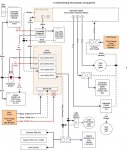
With some free time on my hands, I'm finally getting to rewire my pool house and finish setting up all the automation. I had purchased everything last year, but just didn't have time to complete before the weather got back last year. I thought this diagram might be helpful for others, and I always love feedback! This doesn't show any of the low voltage connections between controllers and valves/sensors/etc.
Some big improvements:
* added safety shutoff switch on outside of pool house
* pump circuit is no longer controlled by turning on/off a 240A circuit switch, it is powered to ALWAYS be on, and the PE653 pool controller uses RS485 control to turn on/set speeds
* adds valve controls, plus the P5043ME expansion controller allows me to control BOTH my heat pump and gas heater
* ensures salt water generator can never run (even if on a timer) if the pool pump breaker trips
* subpanel now meets NEC code to be able to shut off all power in the pool house, on all circuits (a 240V and a separate 120V were originally run to the pool house in 1980s)
* all load calcs done to ensure proper wire derating, circuit sizing, etc
Unusual notes about my setup:
* My pool house is wired with two circuits: 120V circuit (landscape lighting) and a 240V (pool equipment). Both are grounded to ground rods. Equipment from all circuits is grounded together.
* Intermatic PE653 relay can support power from three different circuits, in my case I just have two. The landscape light circuit (which includes the pool light transformer) is controlled entirely through the PE653.
* Shutting off the 20A circuit breaker, powers down the PE653, which automatically breaks al the relays for power to all the 120V lanscape circuit.

Last edited:


