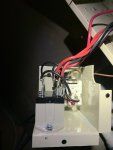
Intermatic timer T104m

SDenman

Member
Jun 7, 2019
9
Monroe, GA
I have the intermatic timers one for the pump and one for the cleaner. I was trying to get my freeze control sensor through the box and got it pinched between the relay and the metal box and fried both( the freeze control and the relay). Now that I have them both replaced the timer for the pump runs much faster that the cleaner timer. I replaced all wires one at a time on the relay to keep from getting them in the wrong spot. Is there and way that I messed up the timer when I burnt up the relay? It’s a mechanical device I can’t see how it would be goofed up but it worked before the accident.
Thanks Seth
 
S,

There is no way you can wire it to make the clocks run fast or slow.. I suspect that you have the "slower" unit being controlled by the "faster" unit?

So basically, the faster unit is running all the time, and the slower unit is only running when the faster unit is giving it power.

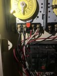
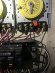
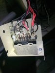
Post some pics of the timers, showing all the wiring inside the boxes.

Thanks,

Jim R.

So the pump timer is getting power because when I manually switch it on it the pump runs but it’s not getting whatever voltage it needs for the little timer gears to run in the back that make it move around. The cleaner timer you can hear run and see the gears turning in the back.
 

Attachments

  • 46853AE4-64A8-4B9D-9856-41C07F748B2B.jpeg
    46853AE4-64A8-4B9D-9856-41C07F748B2B.jpeg
    417.6 KB · Views: 9
  • 0ACC1B4F-B047-4068-A463-EB97D789C36D.jpeg
    0ACC1B4F-B047-4068-A463-EB97D789C36D.jpeg
    427.6 KB · Views: 9
  • A6E0E6F8-DB05-4E83-994E-91160485D33D.jpeg
    A6E0E6F8-DB05-4E83-994E-91160485D33D.jpeg
    296.3 KB · Views: 8
  • 6AD47AF7-8E6F-4C65-9424-AB850C076B78.jpeg
    6AD47AF7-8E6F-4C65-9424-AB850C076B78.jpeg
    311.9 KB · Views: 9
  • 4C487418-51E5-42CB-8275-71B220D27820.jpeg
    4C487418-51E5-42CB-8275-71B220D27820.jpeg
    276.4 KB · Views: 8
On the left timer you have white wires on screws 1 & 3. The thin white wires power the timer wheel. You are missing the white wire timer power connections on the right timer. Find the white wires on the right and connect them to 1 & 3.

It also looks like you are missing ground connections from the timer to the pumps and subpanel.

See upper right wiring diagram in https://www.intermatic.com/-/media/inriver/15269-9112.ashx/T100 Series Instructions EN
 
Last edited:
On the left timer you have white wires on screws 1 & 3. The thin white wires power the timer wheel. You are missing the white wire timer power connections on the right timer. Find the white wires on the right and connect them to 1 & 3.

It also looks like you are missing ground connections from the timer to the pumps and subpanel.

See upper right wiring diagram in https://www.intermatic.com/-/media/inriver/15269-9112.ashx/T100 Series Instructions EN
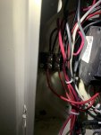
The one on the right has the little white power wires on the distribution block and works fine it can be seen in the 3rd picture it’s kind of hard to see. The timer on the left has the little wires coming off of 1 and 3 and it goes straight to the motor, which is exactly how it was when the pool builder built it. And it has been working fine till I shorted out the relay and freeze control. I put a brand new timer in it today and nothing changed. Everything is grounded I just did not get a picture of that.
 
The one on the right has the little white power wires on the distribution block and works fine it can be seen in the 3rd picture it’s kind of hard to see. The timer on the left has the little wires coming off of 1 and 3 and it goes straight to the motor, which is exactly how it was when the pool builder built it. And it has been working fine till I shorted out the relay and freeze control. I put a brand new timer in it today and nothing changed. Everything is grounded I just did not get a picture of that.
And correction to my original post the pump timer does not run faster it just does not run at all. Sorry for the extra confusion.
 
Which timer dial is not running? Left or right?
 
Seth,

Manually turn on timer one and then see if the clock is now running.. If it is, then you have one of the hot leads connected to the wrong pins..

240 volts should be applied to pins 1 and 3. When the timer is on, the 240 volts will come out pins 2 and 4..

I suspect that you have power going into pins 1 and 4 or 2 and 3... In either case, the clock and pump, will only run when the manual switch is closed.

Do you have a volt meter? If so, use it to test between pins 1 and 3 and see of you have 240 volts.. DO NOT test between a pin and ground as this can give you a false reading with the pump connected... If you have 240 volts between pins 1 and 3 then your clock, or wires to the clock is bad. If you do not have 240 between 1 and 3, test between 1 and 4 and 2 and 3 and see what you get.. These tests done with manual switch off..

Thanks,

Jim R.
 

Enjoying this content?

Support TFP with a donation.

Give Support
Thread Status
Hello , This thread has been inactive for over 60 days. New postings here are unlikely to be seen or responded to by other members. For better visibility, consider Starting A New Thread.