Lighting control question

Don_TLR

0
Silver Supporter
Feb 19, 2018
185
Apache Junction AZ
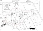
I have 3 different set of lights that I'd like to control independently. The 2 outer lines are for lighting up cactus and planters along with the middle line being for the spa steps.
Can they be controlled with the screen logic and put inside the Easytouch panel or will I have to get 3 separate transformers to do this?
Pool Wall.jpg
 
Don,

In theory, the EasyTouch controls the AC power going to the transformer and then the low voltage from the transformer powers the lights..

To independently control three lights, you would need three relays and three transformers..

No matter what you do, you will need three relays, one for each light.

Having ScreenLogic control the lights is very easy to do, but they have to be wired correctly first.

Thanks,

Jim R.
 
Hey Don/Jim,
Not sure if this idea is strictly legal (although I don't know why it wouldn't be)... but could you mount a single transformer next to the Easytouch panel, control the relays with the Easytouch, but feed them all with the output of the single transformer?

In other words, connect the transfomer's DC/positive output to one side of all 3 relays, and the other side goes to the positive for each of the 3 lightning runs (the grounds for all 3 runs would be tied together to the transformer's negative output).

(of course, you'll want a safety/isolation transformer since one lighting leg is for the spa steps)

Tom
 
Tom,

This would mean you would have in have low voltage wiring in the high voltage area of your power center.. While it would work just fine, the problem is that "what if" one of the low voltage wires came in contact with a high voltage connection. I'm pretty sure they have a seperate Low voltage section and a High voltage section for a reason... :)

Jim R.
 
High and low voltage conductors in the same junction box must be separated by a barrier. Outdated NEC reference: 800-52(a)(1)c.1.Exception 1
 
Hey, sorry... I am not suggesting that any transformer be added to the high voltage area of the panel...

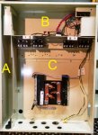
check out the typical Pentair load center:
pentair panel.jpg

Section "A" is a low-voltage chase, section "B" is the low-voltage area, and section "C" is the high voltage area. There are physical barriers here, otherwise the NEC wouldn't allow this panel.

Couldn't you mount a saftey transformer next to the load center, run it's low voltage dc output through Section "A", into section "B" and then connect to the relays at the top of "C"?... and run the output of the relay back into "B" and out through section "A"? (notice that the low-voltage lines from the panel's 24v relay drivers also penetrate into section "C")

Allen, is that prohibited by that code reference you posted?

Tom
 
Tom,

The difference in my mind is that the relay coil wiring does not go out of the box... the relay input from the transformer and the output to the lights both go out of the box...

I guess my point is that the equipment was designed to be wired one way... If someone wants to do another way, I don't have a problem as long as they understand what the correct way is, and why it is that way.. Truth be told, who is going to inspect it?? Unless of course, if something goes wrong...

Thanks,

Jim R.
 
Hey, sorry... I am not suggesting that any transformer be added to the high voltage area of the panel...

check out the typical Pentair load center:
View attachment 93421

Section "A" is a low-voltage chase, section "B" is the low-voltage area, and section "C" is the high voltage area. There are physical barriers here, otherwise the NEC wouldn't allow this panel.

Couldn't you mount a saftey transformer next to the load center, run it's low voltage dc output through Section "A", into section "B" and then connect to the relays at the top of "C"?... and run the output of the relay back into "B" and out through section "A"? (notice that the low-voltage lines from the panel's 24v relay drivers also penetrate into section "C")

Allen, is that prohibited by that code reference you posted?

Tom

Tom, I can’t say for sure that what you propose is to code.

My concern is those relays are placed to switch high voltage. Someone coming along years later and working on the panel may not figure out those lines are low voltage being controlled by a high voltage relay.

If you could mount the aux relays in the low voltage upper section then it would give a clue that those relays are being used for a non standard purpose.

I am more concerned about the safety aspects rather then code. Although most of code is for safety. We see many homeowner wiring hack jobs being figured out by a future owner. I don’t like leaving those traps for the next generation.
 
  • Like
Reactions: MyAZPool
Allen,

Actually that is a great idea that Pentair should consider adding... A whole bank of low voltage relays in a segregated area...

In the old days, everything was 220 or 120, today there are all kinds of things you can control with low voltage.

Thanks,

Jim R.
 

Enjoying this content?

Support TFP with a donation.

Give Support
I don’t know what stuff gets crammed into the upper LV area but it looks like some relays can be installed there with some sheet metal work.
 
I think what the guys are saying - and I agree with them - is that somebody might not notice the difference and there's a possibility of a mistake, which is just plain unsafe. I noticed that the low voltage coil connections for the relays go into the high voltage area, but like Jim said that area is intended to control ac loads.

I really like Allen's suggestion about having a spot for low-voltage relays in the upper section... and I bet the relays could be a lot smaller than the Omrons that are in the panel now. Fitting the Omrons could be tight, there's 3 7/8 inches from the back of the control bezel to the back of the panel... an intellitouch protrudes into that space 1 3/4 inches (ET is less) just for the mainboard/personality combo - without considering the wires - so that leaves just over 2 inches for relays. But then aren't we're back to the point of putting something in there that wasn't intended to be there?
 
  • Like
Reactions: MyAZPool
Thread Status
Hello , This thread has been inactive for over 60 days. New postings here are unlikely to be seen or responded to by other members. For better visibility, consider Starting A New Thread.